PLL Phase Locked Loop on LTSpice

HTML-код
- Опубликовано: 28 сен 2024
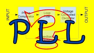
- In this video, Gregory explains the approach used to model, in LTSpice, the Phase Locked Filter loop filter of the 10GHz Microwave Source project.
The Phase and Frequency Detector is analyzed from a small-signal perspective, and its behavior is model on LTSpice, using the standard PLL loop filter. Both closed-loop and open-loop responses are analyzed, with the help of bode plots.
This PLL - Phase Locked Loop is used on the 10GHz source we are developing on the channel.
01:00 - Charge pump PFD
07:14 - Example in LTSpice
09:15 - Modeling the Phase Locked Loop with LTSpice
25:00 - PLL with Prescaler/Frequency Divider
29:30 - Second capacitor in the loop filter
32:00 - Final thoughts
Learn the basics of PLL Loop Filters:
• PLL Loop Filter - The ...
Phase Locked Loop working on the bench:
• 10GHz Microwave Source...
Lean more about the 10GHz Microwave Source project:
• 10GHz Microwave Signal...
Support the channel/new videos being a Patron!
/ allelectronics
Subscribe to the channel to learn more!
#electronicscreators


Support the channel becoming a Patron
patreon.com/allelectronics
I haven't simulated PLLs, but I have simulated numerous opamps. I usually compensated for ~72 degrees of phase margin. At this amount of phase margin the control system will have the best step response (i.e. the shortest settling time). If the closed-loop system is ringing in the time domain, the system doesn't have enough phase margin in the frequency domain.
This is an excellent video with explanation.
Nice video sir, sir if possible, you please make video of standard dual slope ADC in ltspice.
The 0 dB Point of the Loop Filter is the capture Range of the Pll ? Thanks a lot for your Video this Topic isn’t in RUclips at That Level of deepness
For PLLs using the XOR phase detector the capture range is related to the bandwidth, for this phase detector with flip flops no!! The integrator action will always find the lock point
@@AllElectronicsChannel so with this type of pfd the capture range is limited only by the vco range. No?
Yes!!
Thank you for this video. I'm studying this topic right now for my exam at UNI and it always helps watchting some simulations
Thanks for the video, I have a question on 6:32 you said that for large signal the system is always stable, although I feel that the statement is true. But I don't really have a rigorous explanation why this is the case. Do you mind to explain why this is the case?
For large signal, the loop will follow a zero-error condition in a non-linear manner, always working to counterbalance the error. For small-signals we have the current source aproximation.
thanks for the videos!
in 5:30 i don't understand, why 47K ohm and not 50K. also i don't understand why the current is designed to be 50uA ?
47k is a comercial value and 50uA was a good current to generate the gain needed. 500uA was to much and less than 50uA is difficult to deal
The sensitivity of the VCO is a gain factor in the loop and will impact the loop response. The VCO gain, along with the charge pump current, are knobs you can tweak to get the loop response you desire.
Is the phase detector itself really integrator? If the phase difference on the input is constant the output of the detector is also constant, so it seems it is not integrator. VCO is the integrator.
It is. Constant current into a capacitance is integration. The VCO also integrates.
@@AllElectronicsChannel A ok, with the output capacitor it is true. Interesting videos and great explanations.
as always, great!
just a question, when you have a frequency divider on the output can it be just described as a voltage divider on the output of the voltage controlled voltage source in the simulation instead of including it in the phase detector gain value?
Yes!! Is the correct place! I probably would use another voltage controlled voltage source only for the visual, but a resistor divider would work exactly correct!
I want full circuit by single transistors
I want two bottles of wine.
@@AllElectronicsChannel you don't need that you need only ....... Starting
Only two bottles?
You can get there. You need to break down each of the blocks into discrete components, slowly replace each block with your new design implementation.
Hi, thank you for this video, it's really useful!!
I just wanna ask you about the Gain of the VCO, did you set it in rad/(Hz.V)?
what I noticed also is that we always look for the 0dB crossing in the open loop gain, why is that? and why the phase margin needs to be lower by 45°? and most importantly when I choose the values of R and C that provide stability, how can I know their effect in the locking time?
Can you please make a video on digital delay locked loop
Did you copyright the circuit? That's so stupid.
Thanks for loving the content!
Thanks for the explanation and simulation..
😇😇😇
Simulation of delay locked loop on LTSpice would be helpful
I'm using ADIsimPLL, and i'm getting a phase error output of 1.6k deg in the linear region of the chirp, how important is the the phase error, and what's a good typical value?
1600 degrees??
@@AllElectronicsChannel yes it is defined as
Output phase error = (actual VCO phase - target VCO phase)
@@AllElectronicsChannel also it says
"The output phase error can exceed 360 degrees by a very large factor - in fact the phase error can get to N * 360 degrees where N is the main divider ratio. This is because the phase error at the comparison frequency can get to ±360 degrees, so the output phase error gets to ±360N degrees. "
So 1600/N is your actual phase error. If it is constant and you need phase error 0, you need to increase the order of the loop (add and integrator).
@@AllElectronicsChannel so does that mean I have 1600/8 = 200 degrees phase error? (My prescaler is 8) is that close to 180 so I expect an unstable PLL
I made the same schematic as you with the same component values but i found the phase at 10dB instead of -10dB what's the problem 🙏🏻🙏🏻
Inverta as pontas
Can I use this circuit for modulating and demodulating (QPSK) for more than 5 MHz frequency?
True!
Hello, nice explanation man! I would like to know if you have any ideas or experiences with CD4046 used as a FM modulator and demodulator and in what program could it be simulated. I am waiting for your answer or maybe an explanatory video. Wish U the best!
Hello, I never used as such. But as a complete PLL, I'm certain that it may work very well for these applications.
I'll try some schemes, thanks anyway and have a nice day! 😀
In practice,how could I measure op loop curve? If there is not vco feedback into pll, pll won’t work.
If have no idea about nothing, you probably need to poke around with different capacitors and resistors until the loop works.. So you have a starting poing.
I mean that I have pll and vco spec to simulate to get initial loop filter,but I found vco is oscillated with initial loop filter. Then I want to measure gain curve of open loop,How to do this.
If it is completely oscillating you need to play around to stop the oscillation, discovering what is wrong with the model.
If it has ringing, you can excite de loop with a step (changing in input frequency), looking at the VCO voltage. Now you can annotate the parameters, as a 2nd order system, to model it better.