Excellent experiment! If I understand it, your two wires are basically acting as the capacitor in your tuned circuit. I"m interested in making an FM receiver for a fixed frequency, but I guess given capacitor and inductor tolerances, it'd be necessary to tune it manually to get the precise requirement, and then just leave it as it is.
Seems like the two wires might be both acting as a weak capacitor and affecting the resonance of the coil. I don't exactly have the experience to know what's going on there, but that's a cool down and dirty way to work around not having a variable capacitor! Also I'm glad to see someone has tried this circuit. I want to build it but sometimes with these random online circuit diagrams, I'm not sure if they actually work.
This is a cool circuit! i've been trying to find a FM receiver that doesn't use any ICs and i finally found one, BUT i've recreated this circuit on my own breadboard except the diodes and the radioshack speaker i replaced with a three stage bc337 amplifier circuit hooked up to earbuds however no matter what i try i can't seem to get it to work :(
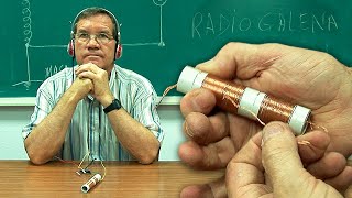
Together, the inductor and capacitor form a resonant (tank) circuit. By varying either the inductor, capacitor, or both, the resonant frequency is changed to the frequency of the station to be heard.
I don't know what the problem is but I have tried both of your fm radio circuits and I can't get either one to work at all. Do you live right next to the station? I first used an lm386 amp with a gain of 200. Then I used an amplified computer speaker for the analog output. The best I could ever get was a low hum that didn't change with tuning. I'm usually pretty good with electronic projects but these have me stumped.


Excellent experiment! If I understand it, your two wires are basically acting as the capacitor in your tuned circuit. I"m interested in making an FM receiver for a fixed frequency, but I guess given capacitor and inductor tolerances, it'd be necessary to tune it manually to get the precise requirement, and then just leave it as it is.
Thank you James for your circuit
Wow that ounds really good for such a simply circuit
Those bread boards have lots of interference(in the form of capacitance)for radio stuff. So placing the LC tank away from the rest is a good idea 😊
Seems like the two wires might be both acting as a weak capacitor and affecting the resonance of the coil. I don't exactly have the experience to know what's going on there, but that's a cool down and dirty way to work around not having a variable capacitor! Also I'm glad to see someone has tried this circuit. I want to build it but sometimes with these random online circuit diagrams, I'm not sure if they actually work.
Very nice 👍👌
This is a cool circuit! i've been trying to find a FM receiver that doesn't use any ICs and i finally found one, BUT i've recreated this circuit on my own breadboard except the diodes and the radioshack speaker i replaced with a three stage bc337 amplifier circuit hooked up to earbuds however no matter what i try i can't seem to get it to work :(
Hello. I have improved the circuit. Check out the video: ruclips.net/video/rVWxFlU52ug/видео.html
That's awesome!
are you using a plastic pen to move the wire to tune because your hand would affect the tuning?
Yes. The pen is to avoid hand capacitance.
your variable resistor is measured in ohms a capacitor is measured in Pf
Haha, just a typo
Nice, did you use 3904 or another transistor? thanks for your help.
Yes. The transistor is a 2N3904.
tronsistor 2n3904. =Bc548
What if I gave each wire it’s own potentiometer?
what is the purpose of the inductor coil....anyone care to comment.
Together, the inductor and capacitor form a resonant (tank) circuit. By varying either the inductor, capacitor, or both, the resonant frequency is changed to the frequency of the station to be heard.
@@jcgoldelectronics1416 ...I'll have to let that sink in some....thanks for the reply ...
What is the function of two transistor?
I don't know what the problem is but I have tried both of your fm radio circuits and I can't get either one to work at all.
Do you live right next to the station?
I first used an lm386 amp with a gain of 200. Then I used an amplified computer speaker for the analog output.
The best I could ever get was a low hum that didn't change with tuning.
I'm usually pretty good with electronic projects but these have me stumped.
Gage of wire used for inductor and turns ,also diameter of turns
We want to send and receive a signal, please