
HTML-код
- Опубликовано: 6 сен 2024
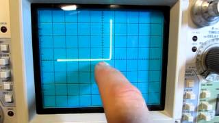
- Just a short video showing how a function generator and an oscilloscope can be used as a very simple, low-voltage / low-power curve tracer to visualize the voltage - current relationship of a device under test (DUT). An alternative technique would be to use an "Octopus" component tester. I did a video on the octopus tester which you can find here:
• #49: Simple Component ...
The video notes for this video can be downloaded here:
www.qsl.net/w2a...


This stuff is so useful! I can’t thank you enough fir the content you've put out. I'm an 'older' self learner in electronic engineering and I find these videos truly exciting
He's amongst the best. I wish he'd enable the thank you button
Thank you so much for sharing this video, because of you I now have a curve tracer on my cheap Hantek digital oscilloscope which is so cool.
I can't believe that I got it working by just copying your circuits, I'll make some more improvements to have some more control and make it a more permanent circuit by soldering it to a strip board, now I've got it working already without having the right components such as not having a rail-to-rail opamp and it's on a breadboard but it still works, man I've had a lot of fun making this circuit.
I followed your video and built a I-V Curve Tracer on a solderless breadboard. And it works. Thanks. I had to solder wires to the 3 BNC connectors though. I got resistors and capacitors to display but I was unable to get diodes to display. So, not idea what I am doing. Anyways, I try again another day. Thanks for your wonderful videos. I see other people have created IV Curve Tracer and then mention your video in their description.
Also check out Mr Carlson's lab where you can build your own curve tracer circuit. Works great!
Paul does some great stuff!
Another great video! Thanks for sharing this. I like that not only I can use this to test certain components but its helping me understand how oscilloscope works, plus understand some electronics basics (current sensing, etc).
Hi, Alan. I just spent the evening creating your setup and playing with it. It works very well and, wow, you get lots of information about what is going on with the component DUT. Very cool! Thanks for all your efforts to teach us.
That moment when you realize this oscilloscope costs almost as much as your car! O_o As a software engineer, I don't think I'll ever complain about the cost of my tools again! Awesome vid!
marcus vinicius Although entry level scopes have gotten rather capable, 4 channel 1Ghz MDO scopes are still expensive. This particular model is available used for about 15k usd.
Thanks, Alan for all your useful and great videos. I have been sharing them with my Electronics class.
I noticed when you were measuring the resistor, you said the slope was the resistance, and I think you really meant conductance. I totally understand how hard it is to not misspeak every once in a while. :-)
Again, thanks!
I recently was using a dedicated peace of equipment caledl an Interceptor, This did this job and a lot more but it was old, very old it ran on a 386 CPU and was built around 1993. I was amazed though to find out that the Base/Emitter junction of a Transistor gave a Zener curve in the third quadrant along with the Diode curve in the first quadrant of course. I was never taught the B/E junction was built like a Zener.
¡¡DAMN GOOD!! Thank you for sharing this, as I take away a great deal of value from this lesson! And so maybe you’ve saved me from throwing my life savings at one of those Tektronix curve tracers that weighs a ton!!
that was clever! now i need to find out whether rigol 1054z supports x-y mode for channel A-B vs C-D for floating V-I!
Great video. I know i say it all the time but i love that scope so much haha. A want, not a need haha
You oughta hook that thing up to one or the other of the LED assemblies in that Harbor Freight flashlight I saw on your bench in a recent video. They have a habit of wiring up all of the LEDs in parallel, so it would be interesting to see if different turnon thresholds would show up in the trace or not.
Hii
This tester is very simple. You just need to make two-lead sine wave generators. x.y -0-180 degree phase angle inverse sine. Drive with popular ic8038 and even better ad9833 generator .or simple oscillator .transformer or transformerless .opamp. voltage is adjustable from 5v ac to 24v and frequency from 50hz to 1000hz. current should not exceed 1ma to 5mA. it is enough to know the logic of a resistor and a coil.
I really love how clean and sharp line is in XY mode on Tek scope. I have Agilent scope and in XY mode it always gives me this very blurry pink line or very spotty one in hi-res mode - no other options available. It happens even if I feed super-clean signal from functional generator.
try using AVG mode
Hello, you have planned to use an ADALM1000 as a two-channel oscilloscope with a function generator to get a equipment connected to a computer where you can store the signatures and then compare generator.
thank you i have a diac connected in serie with a resistance (2 kΩ) . Αpplies a voltage ac ( 36 V rms from a transformer 220Vrsm to 36 Vrms) where i must connect the CH1 and CH2 find the I-V curve of DIAC..THANK YOU
Simple but powerful!
Yet another great video!
Thanks!
Once again excellent work. Thanks.
Eagerly waiting for that next video!
Very cool! Sometimes little things like this make concepts click. The response curve of the diode and LED was interesting. It looked like there was little or no hysteresis in the curve, is that pretty typical?
Hysteresis would only show up at much higher frequencies where the reverse recovery time of the junction comes into play. I was driving with just 1kHz, so there's basically no hysteresis.
Awesome! Thanks!
Super useful, Alan! 👍👌
Do you have any circuit using that same principal using a square wave? The circuit I have used for many years is just 60~ with 12 volts ac and the 'in circuit' test I use a 50 ohm resistor with a sweep current of about 240 ma at the test probes. Then for the 'out circuit' test , I use 3300 ohms instead of the 50 ohms. I'm not sure how well the circuit will work using a square wave? Any feedback will be appreciated! A video would be great, if a square wave works ? Gary Grove , 73's
Square waves don't work well because they transition too fast to draw a smooth curve. Sinewaves, triangle waves and sawtooths work best.
Thanks for sharing your knowledge
My Rigol 1054Z needed some help to get xy working. The tek 2467b verified my setup was working. In the past i've just used the tek for this technique and chalked the rigol as nogo. After fiddling with all the knobs and checking my sanity, eventually setting the trigger for channel 2 >> it just magically popped into a working state. Before, the XY mode just looked like a fuzzy dot, or fuzzy line. Now I can't get it *not* to work. I guess that's a good thing though. Hopefully this helps save someone years of fiddling. >> "something to with trigger while in xy"
What is the best option to obtain the best results for the tests? use the AFG (function generator)? Or build an octopus tester (transformer and resistors)? .... and thanks, Alan, your videos are practical and are full of theory, although I'm not very good at listening to English, they have served me a lot in engineering
The generator gives you more flexibility (adjustable amplitude, frequency, etc.), but you do have to take into account that the current sense voltage is added to the DUT voltage.
@@w2aew iam sorry, you refer a the voltage of AFG not is the same in the DUT? this by the resistor?
What if you used a basic low gain differential amplifier to measure the voltage across the DUT?
That would wok too. Like I said, there are many ways to accomplish this.
working on knee zone can avoid temperature dependance?
Nice video. You could place the scope ground between the dut and the Rs. This way you would not get the voltage error from Rs. The current would show up as negative of course.
That won't work because the AFG output is not isolated.
***** ah, sorry true.
Lars Berntzon Hey, no problem. I do have a function generator that does have an isolated output, so I could've done that. I chose not to because most viewers probably don't have an isolated signal generator. I *did* use this configuration in the Octopus circuit because it uses a transformer to drive the DUT, thus is isolated from ground.
I built an octopus that uses a small isolation transformer, driving a panel mount autotransformer to vary the o.c. voltage(and current through sample resistor). I grounded between d.u.t. and resistor. Since current is on the Y axis just hit the invert button on the scope to give proper polarity for current. Also have two anti-parallel diodes that can be switched in ckt(individually, of course) to give 1/2 wave rectification, in cases where you do not wish to reverse bias the D.U.T.
***** Or you could plug your function generator into a little 3 to 2 adapter that causes it to float
I don't know the difference between a Curve tracer and a Fluke Source Measure Unit SMU to test diodes, transistors, FETS. What is the differences between a curve tracers and a SMU source measure unit?
A curve tracer is specifically designed to sweep the voltages and currents necessary to show a family of characteristics curves for 2- and 3-terminal devices (mainly). A SMU is a precision +/- voltage and current source with precision measurements. It can be setup to sweep voltage or current to generate an IV curve.
It appears from the dotted line in your drawing that the 50 ohm resistor is built into the function generator (for termination?). Is that correct, or does a separate 50 ohm resistor need to be added in series with the function generator? I'm still a noobie.
Also, please verify how a transistor would be connected... Function generator to base, or collector?
Thanks, Alan, for all your great videos!
Most function generators will have the 50 ohm series resistor built in. For this simple application, it generally won't matter if it is there or not. This simple technique is designed only for two-terminal devices, so you can't do a proper curve sweep on a transistor. You'd be able to only look at the individual junctions (base-emitter and base-collector).
@@w2aew Thank you, Alan. This link looks like it might explain the setup for transistors and MOSFETs: www.circuitspecialists.com/blog/using-an-arbitrary-waveform-generator-and-a-digital-storage-oscilloscope-to-create-a-transistor-curve-tracer/ What do you think of it?
What I am after is a DIY curve tracer universal (NPN&PNP Transistors, FETs, diodes, resistors, capacitors, etc.) component tester interface circuit that will allow me to use my existing function generator and oscilloscope. I can find lots of circuits that create the frequency signal, mount the DUT and output the signal for the scope. But, I just don't need the frequency generator front end. Do you have any suggestions? Of course, your video and the link I referenced will accomplish my desires, but it is not in one, neat package.
Thank you for your help.
Well, I have found your video on tracing transistors:
ruclips.net/video/ZOLLoa2fH24/видео.html
Hello, sir. I have just built a function generator using an AD9833 and Arduino, which generates a triangular waveform among others with a 600mV peak-to-peak amplitude.... to the best of my knowledge. What circuit do you recommend using to amplify this signal and bring it to 2V peak-to-peak without interfering with the measurements? Greetings, and thank you for your videos; they are very educational.
Simplest solution would be to feed through a transformer. A low power 120VAC to 24VAC transformer could be used in reverse (have your circuit feed the secondary).
O que é o DUT entre os dois cabos do scope?
ty. superb video. made mine work. capacitors show up square because it's a triangle wave instead of sine wave?
Yes, a linear voltage change results in a constant current (and vice versa), that's why you get the square.
Great! Now I can sort out my Zener collection!
Excellent video...tnx for sharing..
Bud...
So I got both a scope and a Funct Gen - So what exactly do I need to do to create a wave tracer ?
You only need the a 10 ohm resistor and a pair of probes, and a way to connect the generator output to the device you're testing, and the 10 resistor to the other device terminal. It is all clearly explained in the 5 minute video.
Hi sr do you think this would be the same as a curv tracer device. ? Equivalent. Thanks. For your very informative videos.
It is similar, the same way that a bicycle is similar to a motorcycle.
Thanks, so what else can a SMU do besides sweeping the voltage and current? an SMU can measure more than 2 or 3 terminal devices to plot the IV curve?
Here are a few good SMU resources for you:
www.tek.com/learning/what-is-a-source-measure-unit
www.testforce.com/testforce_files/NewsEvents/Source-Meter-Fundamental.pdf
Thanks Alan.
So in this case the Y axis is the measured voltage divided by 10, resulting in a number with a unit of Amps?
I see on the oscilloscope that it says channel 2 has a dimension of 20mv/division, so are you just having it display the voltage straight?
Yes, and yes.
I have built a simple curve tracer that i found on the webthat use a function generator instead the transformer and it works but i don't understand why the trace on the display when the probes are open is not flat horizontally but tilted, the same thing for the capacitors that i measure, the circle is tilted. Can be a cable problem?
Usually due to running the function generator at a higher frequency where you see the capacitive effects of the cables/probes.
good video
I have a huntron tracker 2000 works grea
thanks for sharing
HI, Alan, I have been looking for a reference chart of curve tracer shapes. You would think that to be just a google away, but I am not finding what I am after. Do you have a suggestion for a source, or a link, for a fairly comprehensive chart of typical wave forms? Would it be in a 575/6 manual? I imagine I can download that. Thanks.
Chapter 2 in the Tek 576 manual is loaded with typical curves from different device types:
w140.com/tekwiki/images/7/71/070-0905-01.pdf
Really disappointed that the MSOX3104 wouldn't allow me to do math in the XY mode. I'm guessing the MDO3104 has that functionality? Also, here is the V-I curve of a 1N4727 3V zener diode (i.imgur.com/0e3WuHB.png) I just obtained using your method. Thanks for the video!
***** Looks great. Don't feel too bad, the MDO3000 can't do XY with a Math trace either.
What is your frequency in your experiment. ?
I used 1kHz in this case.
Is slope equal to resistance or conductance?
Really both. The closer to horizontal - the higher the resistance and the lower the conductance. The closer to vertical, the lower the resistance and higher the conductance.
@@w2aew y/x, current/voltage = conductance
Thanks for another really useful video. It took me a while to figure out what a DUT is, but i found out when I read the description. I am a 'newbie ' !!
You did ask for feedback on what videos we wish for and I have a request. I'd love to see a video on selecting a probe to be compatible with an oscilloscope.
Following advice to get a second hand analogue scope I bought a 4 channel Tektronix 2247a, but it only has 1 probe. (I have a new digital scope also).
Would for example a p6138 work fine ?
I assume that cheap imports from china will be a waste of money, but are they fine for a second, third or fourth probe ?
Any pointers would be greatly appreciated.
Thanks again
Good topic for a video. In a nutshell, the most important thing is to look at the spec for the compensation range of the probe and ensure that it covers the input capacitance of your scope. For example, if your scope's input capacitance (printed on the front panel by the input connectors) is 15pF, and the probe's compensation range is 10-20pF, then you're ok. With probes, it's often "you get what you pay for". Used Tek or HP probes are often better than cheap no-name new probes, as long as they weren't abused. The downside to used probes is that they often are missing their full complement of accessories (tips, clips, grounding attachments). With a Tek scope, it is handy to get probes that have the 10x indicator pin on the BNC shell, to tell the scope that it is a 10x probe (so you don't have to remember to account for it).
***** That's fantastic - Thanks for getting back to me. I was just about to buy 4 Tektronix p6138 probes, however the spec is 12-18 pf and my scope is 20pf. I do wonder though whether they may actually be ok because they are 350Mhz probes but my scope is only 100Mhz - I'm guessing that the range of 12-18pf on the p6138 is small because the frequency is so high. I am half tempted to get them and do some tests to see whether my theory is correct; However, my knowledge and abilities are a limiting factor.
One problem that I have a s newbie, is that although I understand that things get much more complicated at high frequencies - I don't know how many hertz we are talking about. I followed your video about measuring an unknown capacitor using a scope - it was a great teaching aid for me - however when I tried it myself, I had picked a very small cap (a few pf) so my capacitance came out much more than the real value. I realised after watching your other video about the importance of good shielding on probes, that it was the capacitance of my wires, breadboard etc. that was causing my readings to be high. I've ordered shielded cables, bnc connectors etc and I plan to redo the tests.
I suppose what I'm saying in all of this is that as a newbie - it would be great to understand where I should work, until I my knowledge has improved. I know now that I should avoid 'high frequencies' but It would be great to quantify that. This also goes for probe selection, scope selection etc. I know that it's good to get a higher range scope - the more Hz the better - but will I ever need a 350Mhz scope? or will a 50Mhz probably cover my needs? I understand that good probes are important (but also expensive) so it would be good to understand when this matters - I guess a cheap probe will be fine at sub Khz frequencies? Again as a newbie - should I focus on learning RF principles at the lowest frequencies and move to the higher stuff later ?
I don't expect you to answer any of this - I am just explaining what is confusing for me. I will try to figure this all out for my self, but it may take me a VERY long time !! Thanks again
Lee Massey No worries. It certainly does take time to get comfortable with these things. I've been working in electronics for well over 30 years, and still learn new things everyday. Issues with "high frequency" generally start to arise when you get above a few MHz. I have a video on scope BW, and how much is enough - might be worth watching. Your measurement BW will be limited by the scope or the probe, whichever is less. As frequencies go up, the more critical things like ground lead length, etc. start to become - as well as careful layout, etc. Solderless breadboards generally don't work too well once you get into HF (a few MHz and above). Best advise, keep playing and learn from every mistake, failure and mis-step. Working through these problems is the best way to learn.
thanks my friend
Hi.In this case are you using just the Function generator and the scope? No transformer and no any other component? If yes,with this way we can measure ESR too?
CYBERRD58 Not really. I have other videos on measuring ESR.
How many volts are you using from FG?
CYBERRD58 Right at 2:26 I mention that I am using 2Vpp. Of course, you are free to use whatever voltage you need based on the device that you are testing.
sorry for the questions, is that I speak Portuguese and do not quite understand English spoken very well, just reading
Thank you for the answers
hello trying to reproduce your setup.
could you give me a range for the resistor to use under the DUT on diagram?
thanks
john
I showed this using a 10 ohm resistor as the current sense resistor.
If the function gen and the scope are both grounded, wouldn't that short out the current sense resistor?
Is the probe being used is a current probe?? What if I don't have a current probe, how can i measure the current? Do help me out
The probes being used are both 10x passive voltage probes. The one that is probing across the 10 ohm resistor is effectively measuring current because it is measuring the voltage drop across the 10 ohm resistor (I=V/R).
@@w2aew Thanks for the reply. What if my range of current is in nA, then will the voltage probes be able to measure the nanoamp current??
@@SherinAThomas You'd have to increase the 10 ohm resistor significantly. 10nA will be VERY hard to measure with this very simple approach. Even using a 1Mohm resistor, 10nA will only give you 10mV, which is quite small to measure with a scope. There are specialized low-current ammeters for measuring such small currents.
@@w2aew Is there any other alternative other than using low current ammeters? because i want to plot the I-V of the memristor device.
@@SherinAThomas Probably one of the best tools to do this with is a Source Measure Unit (SMU), such as the Keithley 2450.
How do I work this way
I want to do V-I trace for a resistor in a board. This resistor is my DUT. The resistor is a pull up resistor in a board with one end connected to VCC (+5VDC) and other end connected to the device. I do i make the setup? I will not be able to connect the 10 ohms resistor in series path for current probe. How to do?
For a simple go/no-go curve trace, take a look at the "octopus" circuit: ruclips.net/video/Gwo3pEH7hUE/видео.html
@@w2aew Thank you for providing the link. Can I use octopus circuit to test any resistors, capacitors, inductors and diodes and transistors in-circuit?
@@sanjayparelkar3912 Not always. In circuit testing is always a compromise because surrounding components appear in parallel with the specific device you are trying to test. The way that something like an octopus is used for in-circuit testing is to have a known good reference for each device that you are testing, so that if there is a failure, it will deviate from the known-good curve. Of course, this can only hint at the bad component because the faulty part could be in parallel with the device you are connected to.
@@w2aewWhat is the frequency at the output 6.3V, is it 60Hz ? I can also use 50Hz right? Also where I should connect the ground? Do I need to connect it to the oscilloscope ground?
@@sanjayparelkar3912 Of course, 50Hz works too. The equipment you're testing should be unpowered and unplugged, so connecting to scope ground is appropriate.
Why is probe 2 set at 20 mV?
This is described at 2:05, the expected voltage across the current sense resistor is small.
Awesome.
Hello. Very Nice vídeo. Can you teste a situation of Hight Frequency Transient with one of your less espensive oscilloscope? Like a mini-motor conect to the eletricity home net.
I'm a geobiologiste and the so call "durty eletricity" it's an important matter of safety at home. I'm from Portugal and I'm already a fun. Thank you very much!!!
ΗΙ where put the ground of channel of osciloscope
Bottom of the 10 ohm resistor, as indicated by the ground symbols shown there and at the scope inputs.
have a computer that is running with this device UNI-T UTD1025CLOscilloscopeI
You can't use that scope - it only has a single channel input. You need a 2-channel scope that can also be put into XY mode.
🌹
what is a dut? Oh device under test. Gotcha
I was scrolling to see for anyone asking this question before I asked it.
thanks .
Hello my friend
now u need to make a video on how to find bad components on a board.
Hello Sir,
Dealing with electronics for amateur hobbies
can you suggest a curve tracker circuit for sound card oscilloscope (scope)
how can I make a curve tracker circuit that will work ideally for the sound card oscilloscope (scope)?
www.zeitnitz.eu/scope_en
unfortunately, I don't have enough money to buy an oscilloscope, so I need to make a curve tracker circuit that works with a sound card oscilloscope, and I'd be very happy if you could help me with that.
Have a look at this video: ruclips.net/video/Gwo3pEH7hUE/видео.html