... Beautiful and clear. Thank you.... In the late forties, I was sitting on the ground, leaning against a galvanized Iron Gate. It started receiving a clear radio signal. I think it must have been the zinc crystals in the galvanizing. This event seemed almost like a miracle, to 9 year old me.
I was cultivating with a tractor out in no where and started clearly hearing a station. Nobody else around for miles. I can only figure it was thru my tooth fillings.
The crystal radio project is great for the younger generation, just I gone to the 1960s period when I was 10 years old I made this project, It was a great Joy to listen, to local radio station broadcast. Now I am 64 years old. Thanks for up loading you and You Tube.Now our younger generation should know how the radio works and be good at fundamentals of electronics.
A foxhole radio is also a crystal radio. There are many, many variations. A foxhole radio usually uses a razor blade and a pencil for the diode, instead of the semiconductor one I've used here. I show how to do that in my "Make Razor Blade Diode for Crystal Radio/Foxhole Radio" video (see the link in the description below this video.) Basically a foxhole radio uses less off-the-shelf parts since there aren't any in a foxhole.
It is called Radio Trench if the ingredients are truly made by yourself and obtained from the local area (such as razors and pencils), usually called a crystal radio because the crystal radio circuit is obtained from a shop/commercial crystal radio. It's called a foxhole radio because... Was it made in a foxhole during the war, or because its structure resembles a tunnel (tube)?
Reminds me of when I made my first crystal set radio receiver in 1956 in Ontario Canada. Your video brought back some wonderful memories. I went on to build Televisions, HAM radio stations, Signal Direction Finders and eventually Computers. Thank you for sharing.
I swear, winding the coil is the most difficult and painstaking part. Especially if you never did that before. Took me a while to find the proper way of winding it and making each turn nicely and the wire ending up sitting close together. So satisfying when it's completely wound and ready to be prepared for the next steps.
The purpose of the short one is to be an inductor. It's inducing current in the longer one. The purpose of the longer one is to resonate with the capacitor at the tuned radio frequency. You might be interested in watching my "How a Crystal Radio Works" video, which goes into all that in great detail and with animations. There's a link to it in the description below this video.
One way is to make a radio transmitter and transmit music to it. You can see me do it in my video "How to Make AM Radio Transmitter". There's a link to it in the description below this video.
I'm glad it helped. Be sure to check the list of my other crystal radio videos in the description below this video, or see my crystal radio playlist on my channel page. The "Crystal Radio Troubleshooting and Tips" should probably be the next one to watch.
Very well done, Rimstar! It looks very primitive, but then the idea is to encourage people to try, and I think this is one of the best videos I have seen in that regard. The capacitor for the volume control is a very nice touch! Thanks for the time an effort you took to make this excellent and instructive video!
Yes, you can use a variable capacitor. To match the coil in this video the capacitor should be in the range 40 picofarads to 355 picofarads if you want to tune in the whole AM radio frequency range.
I don't know of any way to do it using a transformer, not that that means there isn't one, but I've made two amplifiers by other ways. One amplifies it for the earpiece and the other amplifies it so you can listen using a loudspeaker. See my "How to Make Amplifier for Crystal Radio Earphone" and "How to Make Crystal Radio Amplifier for Speaker" videos. There are links to them in the description below this video.
In 100uF, the uF is microfarads, which means that's a capacitor, not a diode. So you definitely can't use it. Any germanium diode will work. I've put a partial list in the description below this video. I haven't tried it but you may also be able to get it working with 5 or more silicon diodes connected together in parallel.
A number of ways. Use a longer antenna. Make sure you have a good ground. Decrease the space between the two coils, though that may cause more interference between radio stations. You could also add an amplifier (e.g. one powered by a battery) but then it would no longer be considered a crystal radio since a crystal radio is one which is powered solely by the incoming radio waves.
There isn't much power here. With a long enough antenna or a strong radio station nearby, you can power a single LED. And you still need a radio station somewhere to use electricity to transmit the radio signal in the first place.
Cool! Be sure to check out the playlist. ruclips.net/p/PLFsZmHTZL-zlSltC6ELZW9PK4ks7wgPRz I made a bunch of related videos on the topic, including troubleshooting and tips and how-it-works.
You can reduce the size of the coil using a cylindrical ferrite core instead. It's around 1cm or 1/2inch in diameter. You can make a smaller capacitor using double sided copper cladding board. I show on of those capacitors in my "Crystal Radio Troubleshooting and Tips" video (there's a link to the it in the description below this video.) You can also buy smaller commercially made air core variable capacitors. I give a link in the description to midnightscience's website if you want to buy one.
Ignore the + and - for the speakers and just connect one speaker wire to the end of the diode that has the stripe nearest it and the other speaker wire to the ground. Having said that, these crystal radios aren't powerful enough to power speakers so you very likely won't hear anything. :( There are many places to get piezo earpieces. The Source has piezo buzzers (part no. 2730059) which you can use as an earpiece. See the description below this video for my other videos where I discuss options.
Those were the days of learning about radios and how they work and how to build them. So many youngsters of todays generation could learn so much from videos like this, but many won't be interested because of computer rubbish. Thank you for this video.
Thanks. You can buy crystal earpieces online. See the description below this video for links. You can use piezo buzzers that you buy at electronics stores like Radio Shack. You can use disk piezo crystals taken from various things. See my "Make Crystal Earphone/Earpiece for Crystal Radio" video for taking one from a microwave oven. You can use normal earbuds. See my "Use Earbuds/Earphones with Crystal Radio" video for that. Links to the videos are in the description below this video.
Have fun! Be sure to check the description below this video for a list of all my other crystal radio videos - there's a lot of helpful information there. And don't hesitate to ask questions.
wilwad if a war came along I'd be on the front line im a decent bloke fairly and I get well Larry wen Apple look at me funny down at the pub. I bounce em round like bunnies I've never broke a law in mi life and if a war came along I'd be on the front.line wig the best of em
That is a very very bad idea. Anyone who activates a transmitter after WWIII, will immediately receive a back up nuclear missile on their head. Radio silence will keep you alive.
A diode is something that allows electrons to flow through it in one direction only. So if your power source is one that make electrons move back and forth in the wire but you have a section of your circuit where you want electrons to go in one direction only, then you'd insert a diode in that section. It's called a "crystal" radio because people used to make the diode by touching a Galena rock crystal with the tip of a wire. Nowadays, a modern semiconductor diode is used instead.
The obvious is adjusting the capacitor and tuning bar on the coil, but I'm sure you've tried that. A longer antenna improves this. Also, you can improve it by moving the two coils closer together, but if you have radio stations that overlap then doing so will make that worse. Also make sure you have a good ground. And you're welcome for the video. I'm glad to see so many people get finding it useful.
Wow ! Relived my childhood. Mine was a simpler one. I used to detach the earpiece of our chunky old telephone. Attach the two ends of a galena crystal to the two electrodes of the earpiece. connect the earth and aerial to each of those electrodes and enjoy the strongest available medium wave. The ground rule was, got to replace the ear piece before Dad gets home
What great memories...I did hours of listening on just a diode and earphone. And on tuned sets I DXed other states at night and even shortwave broadcasts.
Jumpstart Jimbo: Have you uploaded the video about this method? I have a faint memory my elder brother did it in the way you mentioned. We used to listen to the local radio station so clearly. That was 70 years back when I was a small kid. I saw the crystal (so he said, there was no diode or any other thing except the telephone receiver which he bought from the Calcutta second hand market) and with a slider (that is the wiper) we can tune in the radio station. Will you please do a video about this method. I believe many like me will be interested about it and they will be benefitted . Please do it and upload the video if possible. I want tp make like this in memory of my elder brother who is no more in this world. He had curiosity things like this.
They are still online, but it's not the same. In the 70's they had most of what you needed and knowledgeable employees. Towards the end of their retail stores, they had nothing, and their employees didn't know the first thing about electronics.
I use a piezo speaker which I took from a microwave oven, so yes, a piezo speaker should work, assuming you mean one where it's a disk shaped piezo crystal. It's a little quieter than the commercial made piezo crystal earpieces. Cut a short piece from a plastic pen to direct the sound into your ear like I do in my "Make Crystal Earphone/Earpiece for Crystal Radio - Homemade" video. There's a link to it in the description below this video.
This video is a big motivation and knowledge source. Thank you so much for that. I am teaching a lab course and including this as the final project. So I had tried to make it as simple as possible and actually providing kits for every student. In the process, I have gathered the following thoughts: 1) Coil: I find the sliding option a bit challenging and intimidating, although I did get it to work. My modified design is a total of 65 turns, with a small loop at 40th turn. So there are 2 settings, 65 turns with the loop not touched, and 40 turns with the loop grounded. Between these 2 settings, the frequency range is quite good. After all, you just want to get some channels to show off, but not necessarily all the channels. 2) Capacitor: I tried to “improve” your design, but finally realized how good yours is. Thought of parallel plates that some people use, but bowing near enter is unavoidable, while your tube design has no such problem. I also tried other materials to make it more rigid than aluminum foil. I tried flashing materials (aluminum and galvanized steel) but they are too stiff and leave too much gap between the inner and outer tubes, so probably loosing some capacitance for the same size. I wound up using thicker aluminum foil available. I was also concerned about the contact by taping, but convinced myself that contact to capacitors is not that critical, since there is no DC current. 3) Speaker: This is more critical and difficult than I expected. Piezo earphone did not work for me, and it was a bit expensive ($7) and I returned it. Piezo buzzer (much cheaper) I could hear something but is quite faint, so hard to tune channels. I also tried piezo transducer, and it did not work. The best I used was a guitar amp, but not everybody has one. Next I will try are PC speaker and headphone (both suggested by your viewers). 4) Wish I could show a photo of my final project, but I did not see that option. Again thanks a million. It’s nice to see old school is kept and being pursued. I am retired and always wanted to do it. Well I finally did!
Thanks for sharing all that. I've had the same problem when teaching a class, having to find the cheapest and simplest way that works. So I can relate. I'm glad to hear it worked out.
my first crystal radio was from junk parts when I was 8yrs old...I changed the diameter and turns of the inductor and used a variable ganged capacitor from an old Crosley AM radio...hooked up to guy wire on house antenna and ground to pipe in kitchen sink...had to buy the earpiece, from Allied Radio store...at late nite I could pick up international shortwave radio signals...have been in electronics ever since...still have my General Class Ham license too! 73, good video!
+Judy Bennett Yes, you can use a small battery power speaker in place of the earpiece. I do that here with my portable crystal radio ruclips.net/video/JtPwxbOgBHw/видео.html which I show how to make here ruclips.net/video/iunAvz9PbN0/видео.html. Though before you think of making this portable one instead, I couldn't get it to work in one building due to the use of a loop antenna. Long, straight wire antennas are better, so I used the crystal radio in this video and stretched wires along the floor for the antenna. Regarding getting a ground, in the first video I link to above, the one about the amplifier, if you look closely you'll see I have my hand on one of the capacitor plates. In that case your body acts as the ground. Doing that, in combination with using an amplifier works fairly well. Your PVC pipe should work fine. The difference isn't that big. PS There's no Reply button under your comment because of your Google+ settings. - go to your Google+ page, - in the top, right corner click on your thumbnail icon, - in the popup that appears, click on "Settings". - for the 2nd question down "Who can comment on your public posts?" set it to "Anyone".
Judy Bennett Also, when do I have to be touching the capacitor? Is there a specific time when that is necessary, or is the radio active all the time? Can I use the speaker for this radio, or will it only work for the portable one? Thanks again!
Judy Bennett You'd have to be touching the capacitor whenever you want to hear the radio. And don't just touch with your finger. The more area your hand contacts the better. You can have visitors to your booth put there hands on it to listen too. The speaker will work with both radios.
I never thought to look in an old smoke alarm. Thanks! They definitely sound like peizo buzzers. And yes, this coil and capacitor are for tuning in 540kHz to 1.6MHz. I'm away from my own computer this week otherwise I could easily calculate what's needed for 198kHz but I'm pretty sure you need more turns.
I can't believe what I see. Just genious. I love how you build all this beautiful things starting from scratch. Well...I should say way less than scratch! I've never seen anybody making a capacitor that way. Could you please answer my question? Please I'm very inquiring: How the hell is the circuit removing the carrier wave from the audio signal wave? I suppose it's impossible to do that on an FM signal using such a simple circuit so I think the input signal you're receiving must be AM. But still, I can't see any LP filter or anything else to remove the carrier wave. How is the circuit doing that? Thank you again for all the knowledge, entertainment and ispiration you give to me.
That's a neat question, because the answer is so sneaky. :) The first obvious thing is that the diode chops off one polarity of the wave. Next, the piezoelectric crystal in the earpiece can't respond fast enough to each peak and zeroing of the carrier wave, so it responds slowly to the peaks only. The result is that the earpiece keeps up only with the audio wave. You can see this illustrated in my "How a Crystal Radio Works" video ruclips.net/video/0-PParSmwtE/видео.html at around 9:27.
I'm sorry, I found the explanation video just after I posted the question, now it's all perfectly clear. Thanks a lot, really. I was looking for a simple RF receiver but I just couldn't find a very basic one to understand, now I did, thank you again :)
I have to do that too sometimes. Usually I check all my connections, including my ground connection, and then I don't have to. I suspect two possibilities, that doing so changes the capacitance or grounds the foil.
The antenna doesn't need to be hung. I use 3 15 foot wires connected in parallel and run across my floor. Though if your floor is metal then there may be a problem. The higher up you go in the air the better, but mine works fine on my hardwood floor.
+Gabriels Raitis Kuma No, an LED won't work. The voltage required to start the LED conducting is too high for the radio. And it has to be a germanium diode, not a silicon diode. PS. Your comment doesn't have a Reply button because your Google+ settings are set to not allow "Anyone" to comment on your public posts.
I bought the lowest voltage drop Schottky diode (0.29v @ 5mA) with very small leakage (within nanoamps) but I have not had luck so far. I suspect my crystal earpiece may have been damaged though.
RimstarOrg I can pick up noise around 700KHz, and it sounds exactly the same on a surround sound system on the AM tuner selection. I think it is my PS3 or TV tuner. Even the tuner cannot pick up any strong AM stations, so if this does work, it is not very sensitive. I have had a germanium diode many years ago and that worked, but a HV transient popped it.
I am 73 and have two crystal radios one I made with a razor blade as the tuner in stead of the wiper . I can get three station one is 35 miles away wwva large powered station
Yeah, remember that trick. Glue a razor blade flat on a wooden board, fix the head of a safety pin near it with a nail, touch the sharp point of the pin vertically on the flat surface of the blade. That'll work as a crude diode
That's actually why I made my first crystal radio, to see how much power I could get. It wasn't enough to pursue it further though. So I guess that's the problem with it. Of course after that I was hooked on the radio part of it anyway. And I'm glad you liked my instructions! Thanks for the feedback!
Yes, the other end needs to be grounded. Without it being grounded it won't work as well. The ground provides an easy path for the electrons to take. See my video "How a Crystal Radio Works" at 0:40. There's a link to it in the description below this video or you can find it on my channel page.
There is no crystal. In the original crystal radios from the early 1900s they did use a crystal instead of the modern diode and that's where they got the name crystal radio. But these days a crystal radio is any radio that gets its power from the incoming radio waves.
I'm actually working on a video explaining how many turns now, but it won't be out for a week or so. The capacitor and coil form an LC resonant circuit. It doesn't have to do with wavelength the way you seem to be thinking about it though. In the meantime, I have some calculators here rimstar.org/science_electronics_projects/lc_circuit_aka_tank_or_resonant_circuit.htm for working out the right coil. I also talk explain it in my How a Crystal Radio Works video ruclips.net/video/0-PParSmwtE/видео.html.
Typically, no, a silicon diode won't work. For that you either need a very long, straight antenna (over 100 feet) or to be next to a powerful radio station. And yes, you can use less turns. You just may have more overlapping stations since you're compressing them into a smaller length of coil for tuning purposes.
I show another DIY design in my crystal radio tips and tricks video ruclips.net/video/HZZmKZJrIW0/видео.html. I have some links to where you can buy on in the video description.
Sir I'm working on this project and I have two questions 1. can we have any other option for grounding because it may be dangerous and I want to make it portable. 2. Can we use one earphones piece for sound will it be much sensitive to sound. Sir plz help its my project
The capacitor and coil are both used for tuning. They form what's called an LC network. L represents the coil (actually the coil's inductance) and C represents the capacitor's capacitance. When the inductance and capacitance are adjusted just right for a particular radio station, then the coil and capacitor resonate with each other, exchanging energy back and forth. The frequency they resonate at is the radio station's frequency. See my "How a Crystal Radio Works" video for more.
Originally the diode was often a galena crystal and the sharp tip of a wire or metal object pressed was against it until a sound was heard. Electrical contact to this diode was made with the crystal and the wire. Then when modern commercial diodes came along, most people switched to using those instead. Nowadays, a crystal radio is defined as a radio that gets its power from the incoming radio waves.
Yeah i too did that on the ends of each wire. However i would not recommend doing that instead of sanding off the coating layer for the wiper. You only wanna wear off the upper layer, not the whole coating all around the coil on that spot.
No, if doesn't matter what part the positive and negative terminals are connected. It doesn't matter which side of the capacitor is grounded as long as the circuit remains the same i.e. don't ground the diode. Touching it doesn't provide a good enough ground, although someone below said they had luck that way by wrapping aluminum foil around their finger and then connecting to the foil for ground, thereby contacting more skin surface area. How long is you antenna? The longer the better.
No. The antenna has to be a long straight wire, either with the crystal radio attached to the middle or to one end. It also helps if the antenna is pointing at the radio station.
1N4148 is a silicon diode. You need a germanium diode. I haven't tried it myself, but someone here reported it works if you use 5 silicon diodes in parallel, meaning connect all their striped sides together and all their non-striped sides together. You can't use normal speakers. You can use normal earbuds (like iPod earbuds for example) using the trick in my "Use Earbuds/Earphones with Crystal Radio" video. There's a link to it in the description below this video or see my channel page.
A 10 meter antenna is good, better than what I have. It doesn't matter if you have more than 90 turns if you will be tuning the coil, in other words if you have a tuning bar or stiff wire that moves over the coil like you mentioned in an earlier post. The other end of the tuning bar/stiff wire will be connected to ground and so will one end of the 90 turn coil, so any turns on the far side of the tuning bar/stiff wire won't be involved in the circuit anyway.
I don't have any immediate plans to make one that runs on a battery, though there seems to be some interest lately so I'll add it to my todo list and think about it.
No, a crystal radio doesn't require batteries. It gets its power from the incoming radio waves themselves. That's what makes these so fun to work with. But it also means that unless you have a very long antenna and a good ground connection or a radio station nearby, then you'll either have trouble getting something or it will be very quiet. Plus, you'll usually need earphones to listen to it, not a speaker. Or you could add an amplifier circuit, but that's no longer a crystal radio :).
The name, Crystal radio, is mostly historical. Instead of a modern diode people used to use actual rock crystals, like galena, and touch it with the tip of a bare wire. This was called a cat's whisker in case you want to look it up. Some people still do that but I've haven't tried it yet. And I already have a video explaining how it works. See the description below this video for a link to my very detailed "How a Crystal Radio Works" video or find it on my channel page.
I just want to say thank you! It's amazing that all the knowledge one could want is on the internet for free. We all owe gratitude to you and to people like you who take the time to share your knowledge with the world.
Back when I was around 8 years old, for Christmas, in the mid 1960s, I was given a "Lectron" set, which was encapsulated electronic components, in little blocks with square tops sowing standard circuit diagram symbols, with magnets for the internal contacts to link with other blocks, on a metal sheet (for a ground, I imagine). I enjoyed some success with most of the projects in the accompanying booklet. However, I could never get the crystal radio project to work at all. That made me sad, and with no support, I gave up. Today, listening to someone go on about crystals in a way that suggested someone hurt her, in the name of actual science, in her formative years. That's what reminded me about "crystal radios." I still don't understand the "crystal" part (Maybe that's the diode?), but your video was a lot of fun, and some healing. Thank you.
Yes, the "crystal" part is the diode, or was the diode. Back in the early 1900s and galena crystal with the sharp tip of a wire touching it was used where today we use the diode. Today, a crystal radio is defined as any radio that is powered by the incoming radio waves.
As a kid I remember having little radios that you would alligator clip to something metallic (like a window) and it would receive AM via a standard earphone. We called them crystal radios. I remember them as being quite small and working well.
Thanks for letting me know. I'm glad to hear it worked. I've wanted to try using a ferrite core for a while now but just haven't had the time to yet. I had to look up what a variometer is. I doubt that I'll make one but thanks for suggesting anyway.
How long is your antenna? 1N4148 is a silicon diode. That and the zener and avalanche diodes need more voltage to start conducting than mine with my three parallel 15 foot antennas. I'm guess either you're antenna is pretty long or you're near some powerful radio stations. Let me know so I'll know if I should add them to the list in the description below this video with a caveat.
A really good antenna length for the entire AM radio range is 139 meters (455 feet). That`s 1/4 the length of a wave with a frequency of 540 kilohertz. but few people are going to be able to do that. So just make it as long as you can. The gauge of the wire makes more of a difference for strength than for the electrical characteristics. A 100 foot 24 gauge strung between two polls might break in a strong wind. So if it`s not suspended in the air or it`s not permanent then use what you have.
Yes, but you'll have to add a transformer. To see the details watch my video "Use Earbuds/Earphones with Crystal Radio". There's a link to it in the description below this video and you can find it on my channel page. (I seem to have a video for everything :)).
Neat design. I've never made a crystal radio with a tuning capacitor 'and' a slider before. Didn't even know you could still get crystal earphones. 5 years too late, but thanks for the video. 👍
I just lay a long length of wire across my floor. Mine isn't very long, only around 3 meters, but I pick up a few nearby radio stations and a few that are a few hundred kilometers away. Most of the time I actually lay out three wires parallel to each other and connect them together at the radio. The diameter of wire (wire gauge) doesn't matter much. Longer is better. And if you have one radio station you always listen to, point the wire at that station if possible.
Funny you should mention that... I'm working on a video right now about an amplifier I made this week. It's a little fancier though with an LM386 amplifier chip and all nicely packaged up. Getting really loud sound with a 9 volt battery. It should be ready next week sometime. But I see your point. Given the amplification that would allow for more options.
Yes, your understanding is correct. However, the problem is that the amount of power you're getting it tiny. With a long enough antenna you can light an LED.
I'm glad my videos are helping! Thanks for letting me know. 0.3v is good, mine isn't that high. So I'd say you're on the right track. Let us know how it goes.
I'm glad to hear it worked. Are you sure you have a germanium diode? One reason a germanium diode is important for the particular crystal radio circuit is that germanium diodes are a bit leaky, which is needed for reasons explained in my How a Crystal Radio Works video. I suspect either you have a germanium diode and some current is leaking through the high resistance of your body, helping with the leakage, or you've a silicon diode and your body is providing the needed leakage. Just a guess.
According to the packaging you're supposed to give it anything from 4 volts to 28 volts. But that's for when it's being used as a loud buzzer. With my crystal radio it's getting only around a few hundred millivolts at most, and of course the resulting sound is pretty quiet.
You could probably make a pocket sized one if it's battery powered, so it wouldn't need a long antenna and a good ground connection. The most portable one I've made that doesn't require batteries is the one I put in my pizza box which you can see in my "Portable Crystal Radio using Loop Antenna and Pizza Box" video (see link in the description to this video or on my channel page.) You can probably make that smaller by making a more compact variable capacitor and folding up the loop antenna coil.
Two diodes in parallel in the same direction, side-by-side would help. A full wave rectifier wouldn't work. Do you mean as when you put the "phone on speaker" so everyone in the room can hear it? If so, you'll likely need an amplifier circuit. If you mean a piezo speaker in the listening end of a phone then just extract the crystal and use it as in the video. If an electromagnet type speaker then you might be able to use the trick I use in my "Use Earbuds/Earphones with Crystal Radio" video.
I've bought mine online and some from stores locally. There's a link in the description below this video to where you can buy them, but there are many, many places online that you can get 1n34s. They're pretty cheap. I really don't know where you can find them in junk electronics. I usually find resistors, capacitors, transformers, cores, but I've never taken out any diodes. Maybe from old radios?
A Schottky diode wouldn't normally work with this circuit. However, I haven't tried it myself but it's been reported below that 5 silicon diodes wired in parallel worked, possibly doing the same with Schottky diodes would work. I wouldn't guarantee it though. Parallel means all the ends with the stripes connected together and all the ends without the strips connected together and use where the diode normally goes.
That is a very novel way of making a variable capacitor. I've spent 38 years as an EE and I'm having one of those "Why the heck haven't I thought of that?" moments. I've been working on some high voltage projects (Tesla coils, Jacob's ladders, plasma arc speakers, etc.) in my spare time and I need some high voltage variable capacitors to tune the circuits. I'm going to try this with adhesive-backed aluminum tape and ABS pipe. I've been struggling with how to do it and you may have just solved my problem. BTW, it's nice to see that people are still building crystal radio sets. Here in Illinois, we have a town named Galena because of all the lead ore they used to mine. It's kind of touristy now, but you can buy all the galena crystals you ever wanted. Poking around on a galena crystal with a 'cat's whisker' to find a sensitive spot is magic! Many crystal radios, even modern ones, are truly works of art. Great video! Thanks for making it.
I'm glad to hear you got some value from the video and enjoyed it so much! Thanks! Regarding the variable capacitor made this way, there is something non-obvious to watch out for if you're using it for high voltage. Using aluminum tape on the ABS pipe is good since it won't move. But if you use a loose foil, as is done here for the other plate then the high voltage will make that plate be attracted to the ABS pipe plate. Since it's just a relatively loose foil, some of it will actually attract and then relax again in time to the frequency, or as close to it as it can. Since one parameter to capacitance is the distance between the plates, that means the capacitance will be varying, even when you think you have it just where you want it. So for the outer plate/cylinder, come up with something rigid.
1) The radio frequency's too fast to notice even if you were to make it turn a light on and off or make a sound. You can calculate it roughly by measuring or calculating the capacitance of the capacitor and the inductance of the coil and using those in the the formula for the resonant frequency. You'll have to look up the formulas for how to calculate the capacitance of a cylindrical capacitor and the inductance but you can see the rest in my How a Crystal Radio Works video starting at 3:36.
I can't say for certain which transformer would work but 230V has as much a chance of working as my 120V one did, so it's worth a try. It's actually the resistance of the transformer windings that's important, not the voltage.
Thanks for posting, I built one of these while helping my granddaughter build another one for a school science project. I only have one good AM station in the area and it I could barley hear it and it was a little garbled... I connected a 47k resistor across the crystal radio ear bud connections and it improved the sound from barley hear it to loud and clear! Thanks again and hope someone finds this comment helpful.
Yup. My understanding is that the resistor helps when the diode doesn't have enough reverse leakage. I explain it in my How a Crystal Radio Works video ruclips.net/video/0-PParSmwtE/видео.html starting at around two minutes and four seconds in.
I was looking for my original crystal radio set I got way back in 1957. It actually had a little crystal item with crystal it it and a filler item you taped on the crystal until you found a radio station. A very simple unit.
Ah, a few problems then. An 8 feet antenna isn't very long, unless you have radio stations nearby. I do and with my three parallel 15 foot antennas, the stations come in fairly quiet. Good innovation with your ground, hopefully it's enough in the ground. The wetter the ground the better. But I just checked 1n4148 and it's a silicon diode. With your short antenna, I'm doubting you'd get the voltage needed for the diode to conduct. Maybe try two or three in parallel or find a germanium diode.
Any kind of wire will do for the antenna, including the magnet wire. The only part you have to bare is the end where you'll connect it to the rest of the circuit.
You could also try a razor blade and pencil diode. I found it very hard to get working but it's another option. See my recent video "Make Razor Blade Diode for Crystal Radio/Foxhole Radio". There's a link to it in the description below this video and on my channel page.
That would depend on what amplifier circuit your battery is powering. In my "How to Make Amplifier for Crystal Radio Earphone" video which just amplifies the sound going into my earphone I use a 9 volt battery. If you're curious there's a link to the video in the description below this video.
when i was a kid back in the 50's and 60's i had these little red pocket type crystal radios that we bought at the store and inside it was kinda like you made there. i had so much fun with that thing, i could listen to baseball games and music at night in bed after lights out with the little earpiece. i used to hook the alligator clip to the radiator pipe. i still listen to a lot of radio today but i'm worried about the future of radio today especially AM with all the other media now.


... Beautiful and clear. Thank you.... In the late forties, I was sitting on the ground, leaning against a galvanized Iron Gate. It started receiving a clear radio signal. I think it must have been the zinc crystals in the galvanizing. This event seemed almost like a miracle, to 9 year old me.
I was cultivating with a tractor out in no where and started clearly hearing a station. Nobody else around for miles. I can only figure it was thru my tooth fillings.
Like in the 1940s? wow
@@martinkennard1669same thing happened to me in school after I got a new tooth filling.
The crystal radio project is great for the younger generation, just I gone to the 1960s period when I was 10 years old I made this project, It was a great Joy to listen, to local radio station broadcast. Now I am 64 years old. Thanks for up loading you and You Tube.Now our younger generation should know how the radio works and be good at fundamentals of electronics.
The power source is the incoming radio waves themselves. So basically the radio station is providing the power when it transmits the waves.
If I had a son/daughter I would watch this with them and build a radio. Builds bonds and teaches them things. Amazing vid, thanks.
I'd do that
Can I be your son/daughter?
Build my first radio, very similar to this, with my dad when I was young, great memory.
honest reaction : Fascinated 😆😃😄✨✨
A foxhole radio is also a crystal radio. There are many, many variations. A foxhole radio usually uses a razor blade and a pencil for the diode, instead of the semiconductor one I've used here. I show how to do that in my "Make Razor Blade Diode for Crystal Radio/Foxhole Radio" video (see the link in the description below this video.) Basically a foxhole radio uses less off-the-shelf parts since there aren't any in a foxhole.
I made a foxhole radio as a kid, much older now.
It is called Radio Trench if the ingredients are truly made by yourself and obtained from the local area (such as razors and pencils),
usually called a crystal radio because the crystal radio circuit is obtained from a shop/commercial crystal radio.
It's called a foxhole radio because... Was it made in a foxhole during the war, or because its structure resembles a tunnel (tube)?
Reminds me of when I made my first crystal set radio receiver in 1956 in Ontario Canada. Your video brought back some wonderful memories. I went on to build Televisions, HAM radio stations, Signal Direction Finders and eventually Computers. Thank you for sharing.
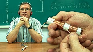
I swear, winding the coil is the most difficult and painstaking part. Especially if you never did that before. Took me a while to find the proper way of winding it and making each turn nicely and the wire ending up sitting close together. So satisfying when it's completely wound and ready to be prepared for the next steps.
The purpose of the short one is to be an inductor. It's inducing current in the longer one. The purpose of the longer one is to resonate with the capacitor at the tuned radio frequency. You might be interested in watching my "How a Crystal Radio Works" video, which goes into all that in great detail and with animations. There's a link to it in the description below this video.
One way is to make a radio transmitter and transmit music to it. You can see me do it in my video "How to Make AM Radio Transmitter". There's a link to it in the description below this video.
I'm glad it helped. Be sure to check the list of my other crystal radio videos in the description below this video, or see my crystal radio playlist on my channel page. The "Crystal Radio Troubleshooting and Tips" should probably be the next one to watch.
I made my first crystal radio, when I was 9 years old, I had a comic book instructed you how to make one. And it worked great at the time.
""Superboy's Workshop" How to Make a Razor-Blade Radio!" Last reprinted in Four Star Spectacular #4, Oct. 1976!
Probably comic book page is :i.pinimg.com/originals/b7/cc/a3/b7cca337dc4a239b60f9aeab203877e8.jpg
That book is worth real money today
Very well done, Rimstar! It looks very primitive, but then the idea is to encourage people to try, and I think this is one of the best videos I have seen in that regard. The capacitor for the volume control is a very nice touch! Thanks for the time an effort you took to make this excellent and instructive video!
Yes, you can use a variable capacitor. To match the coil in this video the capacitor should be in the range 40 picofarads to 355 picofarads if you want to tune in the whole AM radio frequency range.
Can this pick up Shortwave?
I don't know of any way to do it using a transformer, not that that means there isn't one, but I've made two amplifiers by other ways. One amplifies it for the earpiece and the other amplifies it so you can listen using a loudspeaker. See my "How to Make Amplifier for Crystal Radio Earphone" and "How to Make Crystal Radio Amplifier for Speaker" videos. There are links to them in the description below this video.
In 100uF, the uF is microfarads, which means that's a capacitor, not a diode. So you definitely can't use it. Any germanium diode will work. I've put a partial list in the description below this video. I haven't tried it but you may also be able to get it working with 5 or more silicon diodes connected together in parallel.
I built one when I was 10, 62 years ago. I was a little more carful in construction but the same circuit. thanks for the memories.
A number of ways. Use a longer antenna. Make sure you have a good ground. Decrease the space between the two coils, though that may cause more interference between radio stations. You could also add an amplifier (e.g. one powered by a battery) but then it would no longer be considered a crystal radio since a crystal radio is one which is powered solely by the incoming radio waves.
Is it the answer to wireless and free electricity
There isn't much power here. With a long enough antenna or a strong radio station nearby, you can power a single LED. And you still need a radio station somewhere to use electricity to transmit the radio signal in the first place.
I've been looking for a simple crystal radio for my young grandson to build. This looks like the perfect project! Thanks!
Cool! Be sure to check out the playlist. ruclips.net/p/PLFsZmHTZL-zlSltC6ELZW9PK4ks7wgPRz I made a bunch of related videos on the topic, including troubleshooting and tips and how-it-works.
I've watch several already. You do a great job!
You can reduce the size of the coil using a cylindrical ferrite core instead. It's around 1cm or 1/2inch in diameter. You can make a smaller capacitor using double sided copper cladding board. I show on of those capacitors in my "Crystal Radio Troubleshooting and Tips" video (there's a link to the it in the description below this video.) You can also buy smaller commercially made air core variable capacitors. I give a link in the description to midnightscience's website if you want to buy one.
Ignore the + and - for the speakers and just connect one speaker wire to the end of the diode that has the stripe nearest it and the other speaker wire to the ground. Having said that, these crystal radios aren't powerful enough to power speakers so you very likely won't hear anything. :( There are many places to get piezo earpieces. The Source has piezo buzzers (part no. 2730059) which you can use as an earpiece. See the description below this video for my other videos where I discuss options.
I have always enjoyed making crystal radio's ... we used to use a germanium crystal. This is an awesome tutorial ... the best I have seen !!!
Those were the days of learning about radios and how they work and how to build them. So many youngsters of todays generation could learn so much from videos like this, but many won't be interested because of computer rubbish. Thank you for this video.
i like computers and learning how things work dont count me out on wanting to learn about this kind of stuff its very interesting
@@freeze0895That's wonderful! Pity there aren't many like you 😊😊
@@mikebledig7208 yeah I agree all of technology is so interesting pcs radios n64s game boys (game boy colors!) there’s so much yet not enough time
i'm a brazilian younger and learning using a computer...
cant believe how simple this is, thank you for taking the time to make this video and showing us this cool experiment :D
Thanks. You can buy crystal earpieces online. See the description below this video for links. You can use piezo buzzers that you buy at electronics stores like Radio Shack. You can use disk piezo crystals taken from various things. See my "Make Crystal Earphone/Earpiece for Crystal Radio" video for taking one from a microwave oven. You can use normal earbuds. See my "Use Earbuds/Earphones with Crystal Radio" video for that. Links to the videos are in the description below this video.
Have fun! Be sure to check the description below this video for a list of all my other crystal radio videos - there's a lot of helpful information there. And don't hesitate to ask questions.
Everybody please pay attention, we will be using these again after WW3
wilwad if a war came along I'd be on the front line im a decent bloke fairly and I get well Larry wen Apple look at me funny down at the pub. I bounce em round like bunnies I've never broke a law in mi life and if a war came along I'd be on the front.line wig the best of em
*british* 100
Probably...and since the internet might get destroyed too, those who posses this knowledge will be the new radio stars. :D
That is a very very bad idea. Anyone who activates a transmitter after WWIII, will immediately receive a back up nuclear missile on their head. Radio silence will keep you alive.
@@videolabguy after it ends tho
The power source is the incoming radio waves themselves. No battery, no plugging into the wall socket.
exactly, this video is not about a crystal radio.
𝙾𝚔,
𝙽𝚘 𝚘𝚗𝚎 𝚊𝚜𝚔𝚎𝚍 𝚎𝚒𝚗𝚜𝚝𝚎𝚒𝚗
@lizzy-o-glicht8051: Who are you talking about??
A diode is something that allows electrons to flow through it in one direction only. So if your power source is one that make electrons move back and forth in the wire but you have a section of your circuit where you want electrons to go in one direction only, then you'd insert a diode in that section. It's called a "crystal" radio because people used to make the diode by touching a Galena rock crystal with the tip of a wire. Nowadays, a modern semiconductor diode is used instead.
You stoopid
𝙱𝚛𝚞𝚑
𝚈𝚎𝚊, 𝚍𝚞𝚑
I have no ground connection in my home what I will do?????please five me answer
@@bhavanabenrathod2706 pretty much all homes have a ground. You can also use exposed copper or gas plumbing for a ground.
The obvious is adjusting the capacitor and tuning bar on the coil, but I'm sure you've tried that. A longer antenna improves this. Also, you can improve it by moving the two coils closer together, but if you have radio stations that overlap then doing so will make that worse. Also make sure you have a good ground. And you're welcome for the video. I'm glad to see so many people get finding it useful.
Really wish that I could have seen this when I was a child.
So much curiosity was dead out without enough information or demonstration like this one.
Wow ! Relived my childhood. Mine was a simpler one. I used to detach the earpiece of our chunky old telephone. Attach the two ends of a galena crystal to the two electrodes of the earpiece. connect the earth and aerial to each of those electrodes and enjoy the strongest available medium wave. The ground rule was, got to replace the ear piece before Dad gets home
Cool! That's definitely about as simple as you can get.
What great memories...I did hours of listening on just a diode and earphone. And on tuned sets I DXed other states at night and even shortwave broadcasts.
Jumpstart Jimbo: Have you uploaded the video about this method? I have a faint memory my elder brother did it in the way you mentioned. We used to listen to the local radio station so clearly. That was 70 years back when I was a small kid. I saw the crystal (so he said, there was no diode or any other thing except the telephone receiver which he bought from the Calcutta second hand market) and with a slider (that is the wiper) we can tune in the radio station. Will you please do a video about this method. I believe many like me will be interested about it and they will be benefitted . Please do it and upload the video if possible. I want tp make like this in memory of my elder brother who is no more in this world. He had curiosity things like this.
This truly is great. The tunable capacitor from foil ! Amazing, high quality video.
Especially as air-variable caps are getting more and more expensive.
R.i.p radio shack
Lol
i remember those days.
Absolutely I've got hundreds of old radios for parts
Long live radio shacks.
They are still online, but it's not the same. In the 70's they had most of what you needed and knowledgeable employees. Towards the end of their retail stores, they had nothing, and their employees didn't know the first thing about electronics.
I use a piezo speaker which I took from a microwave oven, so yes, a piezo speaker should work, assuming you mean one where it's a disk shaped piezo crystal. It's a little quieter than the commercial made piezo crystal earpieces. Cut a short piece from a plastic pen to direct the sound into your ear like I do in my "Make Crystal Earphone/Earpiece for Crystal Radio - Homemade" video. There's a link to it in the description below this video.
Oh, see the links in the description below this video to two places you can buy them online. I have nothing to do with either company.
I made a crystal radio from a kit when i was in the cub scouts at about age 10. It worked!
Richard Turner know how to make a potato radio that actually works?
It more fun to build stuff out of crap
This video is a big motivation and knowledge source. Thank you so much for that. I am teaching a lab course and including this as the final project. So I had tried to make it as simple as possible and actually providing kits for every student. In the process, I have gathered the following thoughts:
1) Coil: I find the sliding option a bit challenging and intimidating, although I did get it to work. My modified design is a total of 65 turns, with a small loop at 40th turn. So there are 2 settings, 65 turns with the loop not touched, and 40 turns with the loop grounded. Between these 2 settings, the frequency range is quite good. After all, you just want to get some channels to show off, but not necessarily all the channels.
2) Capacitor: I tried to “improve” your design, but finally realized how good yours is. Thought of parallel plates that some people use, but bowing near enter is unavoidable, while your tube design has no such problem. I also tried other materials to make it more rigid than aluminum foil. I tried flashing materials (aluminum and galvanized steel) but they are too stiff and leave too much gap between the inner and outer tubes, so probably loosing some capacitance for the same size. I wound up using thicker aluminum foil available. I was also concerned about the contact by taping, but convinced myself that contact to capacitors is not that critical, since there is no DC current.
3) Speaker: This is more critical and difficult than I expected. Piezo earphone did not work for me, and it was a bit expensive ($7) and I returned it. Piezo buzzer (much cheaper) I could hear something but is quite faint, so hard to tune channels. I also tried piezo transducer, and it did not work. The best I used was a guitar amp, but not everybody has one. Next I will try are PC speaker and headphone (both suggested by your viewers).
4) Wish I could show a photo of my final project, but I did not see that option.
Again thanks a million. It’s nice to see old school is kept and being pursued. I am retired and always wanted to do it. Well I finally did!
Thanks for sharing all that. I've had the same problem when teaching a class, having to find the cheapest and simplest way that works. So I can relate. I'm glad to hear it worked out.
Ah, I see what you mean now. I'll be doing a variometer when I use my ferrite core, I just was familiar with the term. Thanks.
my first crystal radio was from junk parts when I was 8yrs old...I changed the diameter and turns of the inductor and used a variable ganged capacitor from an old Crosley AM radio...hooked up to guy wire on house antenna and ground to pipe in kitchen sink...had to buy the earpiece, from Allied Radio store...at late nite I could pick up international shortwave radio signals...have been in electronics ever since...still have my General Class Ham license too! 73, good video!
+Judy Bennett Yes, you can use a small battery power speaker in place of the earpiece. I do that here with my portable crystal radio ruclips.net/video/JtPwxbOgBHw/видео.html which I show how to make here ruclips.net/video/iunAvz9PbN0/видео.html. Though before you think of making this portable one instead, I couldn't get it to work in one building due to the use of a loop antenna. Long, straight wire antennas are better, so I used the crystal radio in this video and stretched wires along the floor for the antenna.
Regarding getting a ground, in the first video I link to above, the one about the amplifier, if you look closely you'll see I have my hand on one of the capacitor plates. In that case your body acts as the ground. Doing that, in combination with using an amplifier works fairly well.
Your PVC pipe should work fine. The difference isn't that big.
PS There's no Reply button under your comment because of your Google+ settings.
- go to your Google+ page,
- in the top, right corner click on your thumbnail icon,
- in the popup that appears, click on "Settings".
- for the 2nd question down "Who can comment on your public posts?" set it to "Anyone".
Thank you! Sorry about the settings. I think I've changed it now.
Judy Bennett Also, when do I have to be touching the capacitor? Is there a specific time when that is necessary, or is the radio active all the time? Can I use the speaker for this radio, or will it only work for the portable one? Thanks again!
Judy Bennett You'd have to be touching the capacitor whenever you want to hear the radio. And don't just touch with your finger. The more area your hand contacts the better. You can have visitors to your booth put there hands on it to listen too. The speaker will work with both radios.
RimstarOrg OK, tthank you!
I never thought to look in an old smoke alarm. Thanks! They definitely sound like peizo buzzers.
And yes, this coil and capacitor are for tuning in 540kHz to 1.6MHz. I'm away from my own computer this week otherwise I could easily calculate what's needed for 198kHz but I'm pretty sure you need more turns.
Thank you! I am going to build this with my 12 year old son.
I can't believe what I see. Just genious. I love how you build all this beautiful things starting from scratch. Well...I should say way less than scratch! I've never seen anybody making a capacitor that way.
Could you please answer my question? Please I'm very inquiring: How the hell is the circuit removing the carrier wave from the audio signal wave? I suppose it's impossible to do that on an FM signal using such a simple circuit so I think the input signal you're receiving must be AM. But still, I can't see any LP filter or anything else to remove the carrier wave. How is the circuit doing that?
Thank you again for all the knowledge, entertainment and ispiration you give to me.
That's a neat question, because the answer is so sneaky. :) The first obvious thing is that the diode chops off one polarity of the wave. Next, the piezoelectric crystal in the earpiece can't respond fast enough to each peak and zeroing of the carrier wave, so it responds slowly to the peaks only. The result is that the earpiece keeps up only with the audio wave. You can see this illustrated in my "How a Crystal Radio Works" video ruclips.net/video/0-PParSmwtE/видео.html at around 9:27.
I'm sorry, I found the explanation video just after I posted the question, now it's all perfectly clear. Thanks a lot, really. I was looking for a simple RF receiver but I just couldn't find a very basic one to understand, now I did, thank you again :)
I have to do that too sometimes. Usually I check all my connections, including my ground connection, and then I don't have to. I suspect two possibilities, that doing so changes the capacitance or grounds the foil.
The antenna doesn't need to be hung. I use 3 15 foot wires connected in parallel and run across my floor. Though if your floor is metal then there may be a problem. The higher up you go in the air the better, but mine works fine on my hardwood floor.
Thanks for the recommendation. I find Crystal Radio: History, Fundamentals, and Design by P.A. Kinzie to be very good too.
+Gabriels Raitis Kuma No, an LED won't work. The voltage required to start the LED conducting is too high for the radio. And it has to be a germanium diode, not a silicon diode.
PS. Your comment doesn't have a Reply button because your Google+ settings are set to not allow "Anyone" to comment on your public posts.
Will an Schottky diode work also?
Some mentioned in the comments here that a low-barrier Schottky barrier might work. I haven't tried it myself.
I bought the lowest voltage drop Schottky diode (0.29v @ 5mA) with very small leakage (within nanoamps) but I have not had luck so far. I suspect my crystal earpiece may have been damaged though.
Thanks. Let me know if you do get it working. It would be nice to have confirmation.
RimstarOrg I can pick up noise around 700KHz, and it sounds exactly the same on a surround sound system on the AM tuner selection. I think it is my PS3 or TV tuner. Even the tuner cannot pick up any strong AM stations, so if this does work, it is not very sensitive. I have had a germanium diode many years ago and that worked, but a HV transient popped it.
I am 73 and have two crystal radios one I made with a razor blade as the tuner in stead of the wiper . I can get three station one is 35 miles away wwva large powered station
That's pretty good for a razor blade one. I know I had trouble getting anything with mine. How long is your antenna?
Over 250 ft I am also on the highest point in my county
george330ful
Wow. 250ft is great, I'm envious. Sounds like a great location.
Yeah, remember that trick. Glue a razor blade flat on a wooden board, fix the head of a safety pin near it with a nail, touch the sharp point of the pin vertically on the flat surface of the blade. That'll work as a crude diode
Jumpstart Jimbo I believe they used to call that a cats whisker
That's actually why I made my first crystal radio, to see how much power I could get. It wasn't enough to pursue it further though. So I guess that's the problem with it. Of course after that I was hooked on the radio part of it anyway.
And I'm glad you liked my instructions! Thanks for the feedback!
Yes, the other end needs to be grounded. Without it being grounded it won't work as well. The ground provides an easy path for the electrons to take. See my video "How a Crystal Radio Works" at 0:40. There's a link to it in the description below this video or you can find it on my channel page.
Can you make a crystal SW radio?
Yes, just make a shorter coil
1:15 = money shot 🐲
:'D :'D :'D Oh god. :3
SB please tell me, what is this? How do you use this? What is it for? Where is the crystal in it because I missed that. Thank you.
There is no crystal. In the original crystal radios from the early 1900s they did use a crystal instead of the modern diode and that's where they got the name crystal radio. But these days a crystal radio is any radio that gets its power from the incoming radio waves.
8:57 25 turn coil and 90 turn coil ?
I'm actually working on a video explaining how many turns now, but it won't be out for a week or so. The capacitor and coil form an LC resonant circuit. It doesn't have to do with wavelength the way you seem to be thinking about it though. In the meantime, I have some calculators here rimstar.org/science_electronics_projects/lc_circuit_aka_tank_or_resonant_circuit.htm for working out the right coil. I also talk explain it in my How a Crystal Radio Works video ruclips.net/video/0-PParSmwtE/видео.html.
can we use silicon diode and less no of turns plz cmnt
Typically, no, a silicon diode won't work. For that you either need a very long, straight antenna (over 100 feet) or to be next to a powerful radio station. And yes, you can use less turns. You just may have more overlapping stations since you're compressing them into a smaller length of coil for tuning purposes.
Thank you for valuable reply
RimstarOrg could you tell me any other alternatives of capacitor (trimmer capacitor)
I show another DIY design in my crystal radio tips and tricks video ruclips.net/video/HZZmKZJrIW0/видео.html. I have some links to where you can buy on in the video description.
Sir I'm working on this project and I have two questions
1. can we have any other option for grounding because it may be dangerous and I want to make it portable.
2. Can we use one earphones piece for sound will it be much sensitive to sound.
Sir plz help its my project
The capacitor and coil are both used for tuning. They form what's called an LC network. L represents the coil (actually the coil's inductance) and C represents the capacitor's capacitance. When the inductance and capacitance are adjusted just right for a particular radio station, then the coil and capacitor resonate with each other, exchanging energy back and forth. The frequency they resonate at is the radio station's frequency. See my "How a Crystal Radio Works" video for more.
Originally the diode was often a galena crystal and the sharp tip of a wire or metal object pressed was against it until a sound was heard. Electrical contact to this diode was made with the crystal and the wire. Then when modern commercial diodes came along, most people switched to using those instead. Nowadays, a crystal radio is defined as a radio that gets its power from the incoming radio waves.
Damn I knew this was a old video the second he said Radio Shack
You can burn the insulation off with a lighter
Yeah i too did that on the ends of each wire. However i would not recommend doing that instead of sanding off the coating layer for the wiper. You only wanna wear off the upper layer, not the whole coating all around the coil on that spot.
u can burn the whole radio with a lighter
I want to make one but I don't think I have the patience. 😂
My antenna is about 10 metters , on the second floor of the house , so its pretty high , the ground is the radiator pipe, it works kind of well.
No, if doesn't matter what part the positive and negative terminals are connected. It doesn't matter which side of the capacitor is grounded as long as the circuit remains the same i.e. don't ground the diode. Touching it doesn't provide a good enough ground, although someone below said they had luck that way by wrapping aluminum foil around their finger and then connecting to the foil for ground, thereby contacting more skin surface area. How long is you antenna? The longer the better.
weirdest meth lab ever
Different strokes for different folks at 1:15 ;D
No. The antenna has to be a long straight wire, either with the crystal radio attached to the middle or to one end. It also helps if the antenna is pointing at the radio station.
1N4148 is a silicon diode. You need a germanium diode. I haven't tried it myself, but someone here reported it works if you use 5 silicon diodes in parallel, meaning connect all their striped sides together and all their non-striped sides together. You can't use normal speakers. You can use normal earbuds (like iPod earbuds for example) using the trick in my "Use Earbuds/Earphones with Crystal Radio" video. There's a link to it in the description below this video or see my channel page.
I agree. Crystal radio's are very simple, yet very rewarding and teach some useful basics.
2) You need a different circuit for transmitting. If you want one, I show how to make a simple on in my "How to Make an AM Radio Transmitter" video.
A 10 meter antenna is good, better than what I have. It doesn't matter if you have more than 90 turns if you will be tuning the coil, in other words if you have a tuning bar or stiff wire that moves over the coil like you mentioned in an earlier post. The other end of the tuning bar/stiff wire will be connected to ground and so will one end of the 90 turn coil, so any turns on the far side of the tuning bar/stiff wire won't be involved in the circuit anyway.
I don't have any immediate plans to make one that runs on a battery, though there seems to be some interest lately so I'll add it to my todo list and think about it.
No, a crystal radio doesn't require batteries. It gets its power from the incoming radio waves themselves. That's what makes these so fun to work with. But it also means that unless you have a very long antenna and a good ground connection or a radio station nearby, then you'll either have trouble getting something or it will be very quiet. Plus, you'll usually need earphones to listen to it, not a speaker. Or you could add an amplifier circuit, but that's no longer a crystal radio :).
The name, Crystal radio, is mostly historical. Instead of a modern diode people used to use actual rock crystals, like galena, and touch it with the tip of a bare wire. This was called a cat's whisker in case you want to look it up. Some people still do that but I've haven't tried it yet.
And I already have a video explaining how it works. See the description below this video for a link to my very detailed "How a Crystal Radio Works" video or find it on my channel page.
I just want to say thank you! It's amazing that all the knowledge one could want is on the internet for free. We all owe gratitude to you and to people like you who take the time to share your knowledge with the world.
Back when I was around 8 years old, for Christmas, in the mid 1960s, I was given a "Lectron" set, which was encapsulated electronic components, in little blocks with square tops sowing standard circuit diagram symbols, with magnets for the internal contacts to link with other blocks, on a metal sheet (for a ground, I imagine).
I enjoyed some success with most of the projects in the accompanying booklet. However, I could never get the crystal radio project to work at all. That made me sad, and with no support, I gave up.
Today, listening to someone go on about crystals in a way that suggested someone hurt her, in the name of actual science, in her formative years. That's what reminded me about "crystal radios." I still don't understand the "crystal" part (Maybe that's the diode?), but your video was a lot of fun, and some healing. Thank you.
Yes, the "crystal" part is the diode, or was the diode. Back in the early 1900s and galena crystal with the sharp tip of a wire touching it was used where today we use the diode. Today, a crystal radio is defined as any radio that is powered by the incoming radio waves.
As a kid I remember having little radios that you would alligator clip to something metallic (like a window) and it would receive AM via a standard earphone. We called them crystal radios. I remember them as being quite small and working well.
Thanks for letting me know. I'm glad to hear it worked. I've wanted to try using a ferrite core for a while now but just haven't had the time to yet. I had to look up what a variometer is. I doubt that I'll make one but thanks for suggesting anyway.
How long is your antenna? 1N4148 is a silicon diode. That and the zener and avalanche diodes need more voltage to start conducting than mine with my three parallel 15 foot antennas. I'm guess either you're antenna is pretty long or you're near some powerful radio stations. Let me know so I'll know if I should add them to the list in the description below this video with a caveat.
A really good antenna length for the entire AM radio range is 139 meters (455 feet). That`s 1/4 the length of a wave with a frequency of 540 kilohertz. but few people are going to be able to do that. So just make it as long as you can. The gauge of the wire makes more of a difference for strength than for the electrical characteristics. A 100 foot 24 gauge strung between two polls might break in a strong wind. So if it`s not suspended in the air or it`s not permanent then use what you have.
Yes, but you'll have to add a transformer. To see the details watch my video "Use Earbuds/Earphones with Crystal Radio". There's a link to it in the description below this video and you can find it on my channel page. (I seem to have a video for everything :)).
Neat design. I've never made a crystal radio with a tuning capacitor 'and' a slider before. Didn't even know you could still get crystal earphones. 5 years too late, but thanks for the video. 👍
I just lay a long length of wire across my floor. Mine isn't very long, only around 3 meters, but I pick up a few nearby radio stations and a few that are a few hundred kilometers away. Most of the time I actually lay out three wires parallel to each other and connect them together at the radio. The diameter of wire (wire gauge) doesn't matter much. Longer is better. And if you have one radio station you always listen to, point the wire at that station if possible.
Funny you should mention that... I'm working on a video right now about an amplifier I made this week. It's a little fancier though with an LM386 amplifier chip and all nicely packaged up. Getting really loud sound with a 9 volt battery. It should be ready next week sometime. But I see your point. Given the amplification that would allow for more options.
Yes, your understanding is correct. However, the problem is that the amount of power you're getting it tiny. With a long enough antenna you can light an LED.
I'm glad my videos are helping! Thanks for letting me know. 0.3v is good, mine isn't that high. So I'd say you're on the right track. Let us know how it goes.
U said that 20 times
Stop complimenting your self
I'm glad to hear it worked. Are you sure you have a germanium diode? One reason a germanium diode is important for the particular crystal radio circuit is that germanium diodes are a bit leaky, which is needed for reasons explained in my How a Crystal Radio Works video. I suspect either you have a germanium diode and some current is leaking through the high resistance of your body, helping with the leakage, or you've a silicon diode and your body is providing the needed leakage. Just a guess.
According to the packaging you're supposed to give it anything from 4 volts to 28 volts. But that's for when it's being used as a loud buzzer. With my crystal radio it's getting only around a few hundred millivolts at most, and of course the resulting sound is pretty quiet.
You could probably make a pocket sized one if it's battery powered, so it wouldn't need a long antenna and a good ground connection. The most portable one I've made that doesn't require batteries is the one I put in my pizza box which you can see in my "Portable Crystal Radio using Loop Antenna and Pizza Box" video (see link in the description to this video or on my channel page.) You can probably make that smaller by making a more compact variable capacitor and folding up the loop antenna coil.
Oh wow this is really good. best tutorial on RUclips for crystal radios for absolute beginners.
Two diodes in parallel in the same direction, side-by-side would help. A full wave rectifier wouldn't work.
Do you mean as when you put the "phone on speaker" so everyone in the room can hear it? If so, you'll likely need an amplifier circuit. If you mean a piezo speaker in the listening end of a phone then just extract the crystal and use it as in the video. If an electromagnet type speaker then you might be able to use the trick I use in my "Use Earbuds/Earphones with Crystal Radio" video.
I've bought mine online and some from stores locally. There's a link in the description below this video to where you can buy them, but there are many, many places online that you can get 1n34s. They're pretty cheap. I really don't know where you can find them in junk electronics. I usually find resistors, capacitors, transformers, cores, but I've never taken out any diodes. Maybe from old radios?
A Schottky diode wouldn't normally work with this circuit. However, I haven't tried it myself but it's been reported below that 5 silicon diodes wired in parallel worked, possibly doing the same with Schottky diodes would work. I wouldn't guarantee it though. Parallel means all the ends with the stripes connected together and all the ends without the strips connected together and use where the diode normally goes.
That is a very novel way of making a variable capacitor. I've spent 38 years as an EE and I'm having one of those "Why the heck haven't I thought of that?" moments. I've been working on some high voltage projects (Tesla coils, Jacob's ladders, plasma arc speakers, etc.) in my spare time and I need some high voltage variable capacitors to tune the circuits. I'm going to try this with adhesive-backed aluminum tape and ABS pipe. I've been struggling with how to do it and you may have just solved my problem. BTW, it's nice to see that people are still building crystal radio sets. Here in Illinois, we have a town named Galena because of all the lead ore they used to mine. It's kind of touristy now, but you can buy all the galena crystals you ever wanted. Poking around on a galena crystal with a 'cat's whisker' to find a sensitive spot is magic! Many crystal radios, even modern ones, are truly works of art. Great video! Thanks for making it.
I'm glad to hear you got some value from the video and enjoyed it so much! Thanks!
Regarding the variable capacitor made this way, there is something non-obvious to watch out for if you're using it for high voltage. Using aluminum tape on the ABS pipe is good since it won't move. But if you use a loose foil, as is done here for the other plate then the high voltage will make that plate be attracted to the ABS pipe plate. Since it's just a relatively loose foil, some of it will actually attract and then relax again in time to the frequency, or as close to it as it can. Since one parameter to capacitance is the distance between the plates, that means the capacitance will be varying, even when you think you have it just where you want it.
So for the outer plate/cylinder, come up with something rigid.
1) The radio frequency's too fast to notice even if you were to make it turn a light on and off or make a sound. You can calculate it roughly by measuring or calculating the capacitance of the capacitor and the inductance of the coil and using those in the the formula for the resonant frequency. You'll have to look up the formulas for how to calculate the capacitance of a cylindrical capacitor and the inductance but you can see the rest in my How a Crystal Radio Works video starting at 3:36.
Great video
Would be great to have a new version that includes a explanation of each part
🎉
Thanks! Already done. My video about how a crystal radio works explains all the parts ruclips.net/video/HupFY_24o-4/видео.html Enjoy!
I can't say for certain which transformer would work but 230V has as much a chance of working as my 120V one did, so it's worth a try. It's actually the resistance of the transformer windings that's important, not the voltage.
Thanks for posting, I built one of these while helping my granddaughter build another one for a school science project. I only have one good AM station in the area and it I could barley hear it and it was a little garbled... I connected a 47k resistor across the crystal radio ear bud connections and it improved the sound from barley hear it to loud and clear! Thanks again and hope someone finds this comment helpful.
Yup. My understanding is that the resistor helps when the diode doesn't have enough reverse leakage. I explain it in my How a Crystal Radio Works video ruclips.net/video/0-PParSmwtE/видео.html starting at around two minutes and four seconds in.
Thanks, great video!
This is fascinating in one respect -- no battery. Impressive
I was looking for my original crystal radio set I got way back in 1957. It actually had a little crystal item with crystal it it and a filler item you taped on the crystal until you found a radio station. A very simple unit.
Ah, a few problems then. An 8 feet antenna isn't very long, unless you have radio stations nearby. I do and with my three parallel 15 foot antennas, the stations come in fairly quiet. Good innovation with your ground, hopefully it's enough in the ground. The wetter the ground the better. But I just checked 1n4148 and it's a silicon diode. With your short antenna, I'm doubting you'd get the voltage needed for the diode to conduct. Maybe try two or three in parallel or find a germanium diode.
Any kind of wire will do for the antenna, including the magnet wire. The only part you have to bare is the end where you'll connect it to the rest of the circuit.
Terrific presentation!
You could also try a razor blade and pencil diode. I found it very hard to get working but it's another option. See my recent video "Make Razor Blade Diode for Crystal Radio/Foxhole Radio". There's a link to it in the description below this video and on my channel page.
That would depend on what amplifier circuit your battery is powering. In my "How to Make Amplifier for Crystal Radio Earphone" video which just amplifies the sound going into my earphone I use a 9 volt battery. If you're curious there's a link to the video in the description below this video.
when i was a kid back in the 50's and 60's i had these little red pocket type crystal radios that we bought at the store and inside it was kinda like you made there. i had so much fun with that thing, i could listen to baseball games and music at night in bed after lights out with the little earpiece. i used to hook the alligator clip to the radiator pipe. i still listen to a lot of radio today but i'm worried about the future of radio today especially AM with all the other media now.