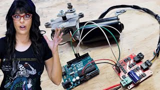
Arduino Fan Control // 2-Wire, 3-Wire, and 4-Wire CPU Fan Speed Control and Measurement

HTML-код
- Опубликовано: 4 окт 2024
- Find Science Fun Innovations, LLC on Facebook @sciencefun4u.
In this tutorial I will show you how to control 2-wire, 3-wire, and 4-wire CPU fans using an Arduino. With 2-wire fans and 3-wire fans, speed control is possible using an N-channel MOSFET and PWM. With 3-wire fans and 4-wire fans, it is possible to measure the fan speed using an Arduino input and a pull-up resistor. With 4-wire fans, speed control is possible directly with a PWM Arduino channel without the use of a transistor or MOSFET.
The Arduino source files are available here: sciencefuninnovation.gumroad.com . Your donations will help me to continue to produce educational and entertaining videos. Thanks for your support!
Look forward to a future video where I will use these fan control techniques to control the fan on a DIY hovercraft. Please subscribe to my channel and help me reach my goal of 1,000 subscribers by the end of 2020. Thanks for watching!


The Arduino source files are available here sciencefuninnovation.gumroad.com/l/ndbytc for a minimal donation. Your donations will help me to continue to produce educational and entertaining videos. Thanks for your support!
If it's mandatory then it's not a "donation". It's "for sale".
2 wire code:
float temperature;
const int fan_control_pin = 3;
void setup() {
pinMode(fan_control_pin, OUTPUT);
digitalWrite(fan_control_pin, LOW);
}
void loop() {
temperature = float(analogRead(A0)) * 500.0 / 1024.0;
if (temperature > 100.0) digitalWrite(fan_control_pin, HIGH);
else digitalWrite(fan_control_pin, LOW);
delay(1000);
}
3 wire fan:
int count = 0;
unsigned long start_time;
int rpm;
void setup() {
Serial.begin(9600);
attachInterrupt(digitalPinToInterrupt(2), counter, RISING);
}
void loop() {
start_time = millis();
count = 0;
while((millis() - start_time) < 1000){
}
rpm = count * 60 / 2;
Serial.print(rpm);
Serial.println(" rpm");
}
void counter() {
count++;
}
4 wire fan:
float temperature;
const int fan_control_pin = 3;
int count = 0;
unsigned long start_time;
int rpm;
void setup() {
pinMode(fan_control_pin, OUTPUT);
analogWrite(fan_control_pin, 0);
Serial.begin(9600);
attachInterrupt(digitalPinToInterrupt(2), counter, RISING);
}
void loop() {
temperature = float(analogRead(A0)) * 500.0 / 1024.0;
if (temperature < 100.0) analogWrite(fan_control_pin, 0);
if ((temperature >= 100.0) && (temperature < 120.0)) analogWrite(fan_control_pin, 126);
if (temperature >= 120.0) analogWrite(fan_control_pin, 255);
start_time = millis();
count = 0;
while((millis() - start_time) < 1000){
}
rpm = count * 60 / 2;
Serial.print("The temperature is ");
Serial.print(temperature);
Serial.print((char)176);
Serial.println("F");
Serial.print("The fan speed is ");
Serial.print(rpm);
Serial.println(" rpm");
}
void counter() {
count++;
}
After trying out 2 fan controllers from amazon, that both were rather dodgy tat, thanks to this tutorial I'm now turning two of my obsolete Arduinos into something actually useful. Thank you very much!
Glad I could help! Thanks for watching.
Excellent how-to video. Gets right to the point with clear instructions. I will add that the wire colors on these fans are not standardized. I have a Delta brand 4 wire fan and black is ground, yellow is +12V, green is tachometer, and blue is PWM input.
Yes. I wish everyone would standardize wire colors for fans, motors, stepper motors, etc!
It's recommended to connect to the mosfet's gate through a current-limiting resistor because the current can be high briefly due to the gate's capacitance (charging when driven high and discharging when driven low). It's also recommended to connect the gate to ground through a pulldown resistor so that it can discharge and turn the mosfet, and thus the device, off when not driven or unpowered (a kind of fail-safe).
That makes sense. Good tip!
This video helps a lot! Starting my electronics journey, I have made a basic inverter circuit with two npn transistors and practiced soldering various thongs. Thought it was time to get an arduino and see how to control these computer fans that i got from a trashed computer, with just an arduino and not have to use a speed controller!
Glad it helped. Good luck!
This is awesome. Just in time for my project. I want to control my radiator fans depending on the coolant temperature.
Good luck!
Thanks. I have been looking for this for quite some time. It works fine...
Glad I could help! Thanks for watching!
FYI It's Gate Drain and Source pins not sink
Good catch, I always get those messed up.
I thought the same, but wasnt sure. But if you think about it a logical way, its wrong, because "drain" and "sink", you can't sink if you don't have a source, right? :D
Great Tutorial! Minor addition: your counter must be volatile, since it is written to by and interrupt and read from the main loop
Great tip! I often forget to do that.
2 wire code:
float temperature;
const int fan_control_pin = 3;
void setup() {
pinMode(fan_control_pin, OUTPUT);
digitalWrite(fan_control_pin, LOW);
}
void loop() {
temperature = float(analogRead(A0)) * 500.0 / 1024.0;
if (temperature > 100.0) digitalWrite(fan_control_pin, HIGH);
else digitalWrite(fan_control_pin, LOW);
delay(1000);
}
3 wire fan:
int count = 0;
unsigned long start_time;
int rpm;
void setup() {
Serial.begin(9600);
attachInterrupt(digitalPinToInterrupt(2), counter, RISING);
}
void loop() {
start_time = millis();
count = 0;
while((millis() - start_time) < 1000){
}
rpm = count * 60 / 2;
Serial.print(rpm);
Serial.println(" rpm");
}
void counter() {
count++;
}
4 wire fan:
float temperature;
const int fan_control_pin = 3;
int count = 0;
unsigned long start_time;
int rpm;
void setup() {
pinMode(fan_control_pin, OUTPUT);
analogWrite(fan_control_pin, 0);
Serial.begin(9600);
attachInterrupt(digitalPinToInterrupt(2), counter, RISING);
}
void loop() {
temperature = float(analogRead(A0)) * 500.0 / 1024.0;
if (temperature < 100.0) analogWrite(fan_control_pin, 0);
if ((temperature >= 100.0) && (temperature < 120.0)) analogWrite(fan_control_pin, 126);
if (temperature >= 120.0) analogWrite(fan_control_pin, 255);
start_time = millis();
count = 0;
while((millis() - start_time) < 1000){
}
rpm = count * 60 / 2;
Serial.print("The temperature is ");
Serial.print(temperature);
Serial.print((char)176);
Serial.println("F");
Serial.print("The fan speed is ");
Serial.print(rpm);
Serial.println(" rpm");
}
void counter() {
count++;
}
,
That was very helpful video. I forgot to connect MCU's GND to power supply's GND. Everything is fine now :)
Glad it's working.
the creativity behind this video is awesome! great video, subscribed!
Thank you so much!
I’m grateful it helpful for me.
Glad it was helpful. Thanks for watching!
Thanks for doing this overview! I just bought a few 2-wire 12v computer fans that I’m going to use to cool some USB hard drives. I was originally planning to just hook them up to a 12v power supply and call it a day, but I thought maybe I could control them with an Arduino (or an ESP8266 to get network control) and did a quick search on RUclips. I’m glad I did because this is exactly he info I needed. I knew I would need some kind of transistor, and could probably PWM control a non-PWM fan, but having the circuit laid out and tested already is going to save me a bunch of research and testing time! Thanks again!
Glad it was useful!
I found your video extremely useful because I was trying to send pulse wave modulation into day 3 pin without a mosfet lol I had no idea that that was a feedback wire
Glad it helped
Glad it was useful! Thanks for watching!
Questions I'm left with after watching:
1. Does the yellow wire go to ground for each pulse?
2. (I rewatched the video, and this one was answered) is pin 2 capable of interrupts
3. What voltage does the PWM controller on the 4-wire fan work with? Min/max?
1) The yellow wire shorts to ground twice per revolution. The pullup resistor allows the wire to go high again in between.
2) Pins 2 & 3 on Arduino Uno/Nano can do interrupts.
3) Not sure, probably different for each fan. 5V seems to always work.
Thanks for your sharing. Your video is informative to me. It really helps me a lot. Again thank you.
Glad to hear that!
Nice video, keep it up, thanks :)
Thanks for watching!
Awesome video, thanks!
Glad you liked it!
Good video, well explained!
Glad you liked it!
I read somewhere that 3-wire fans needs a stable DC voltage via for example a dc-dc converter and not controllable via (high current, in this case not very high current, but it is not a signal PWM just like the 4-wire fans) PWM.
Pure DC voltage (e.g. battery) is usually preferable than pulsed (PWM), especially with brushless motors.
Hi! I have two questions about this project. Great vid btw!
Firstly, why do you connect the ground of the Arduino to the 0V on the power supply? In addition, what Ohm value resistor are you using to connect the 5V to the yellow wire on the fan? I'm a bit of an intermediate but still a total noob sometimes lol, thanks for your help!
Because the fan used 12V from the power supply and the Arduino was powered with a separate 9V battery it is necessary to connect the negatives together (common ground) for the MOSFET to work properly (since the MOSFET is connected to both). Otherwise, the fan might not have turned on/off when commanded. It may have turned on/off randomly, or not worked at all.
For the yellow wire, I think I used a 10K ohm resisitor, but any value over about 5K should work fine. Hope this helps, and thanks for watching!
Nice video Dude 😊👍
Glad you enjoyed it
For the 3 wire fan. Can i use 12v fan with the same instructions in the video?. For the red wire i connect to +12v and -12v from seperate power supply, and is it right to connect the -12v to the arduino's ground like in the video? im a beginner, thank you.
Should be 12V (positive) and 0V (negative or ground). And yes I usually connect all my grounds together.
good job! but i do have a question, would you mind telling me how to vary the voltage to be measured at the pin of the pull up resitor? ( 3 wire fan) thank you.
You can use any pullup voltage that you need. Or you could use a voltage divider if needed to drop the voltage.
Great video. What is the function of the 10K resistor? Can I use a different resistor? What is the min/max I can use?
It holds the wire "HIGH" at 5V. Twice per revolution the fan shorts the wire to ground creating a "LOW". That way the Arduino can watch for the change in state. Any resistor between 1K and 100K should work, but 10k is pretty common.
Too high resistor would provide low current and arduino may not detect it, and a low resistor would provide higher current, more than arduino can handle
@@LakiuGamer But it's not used for current. It pulls the line 'up' (to 5v in this instance) so there's no ambiguity about the state of the line when the fan is not pulsing. When the fan pulses, the line connects to GND and the resistor holds the 5v back for the duration. When the fan disconnects GND, then voltage on that line goes back to 5v via the resistor. The resistor let's you hold the line high (5v) without getting a short circuit.
@@ScienceFunInnovationsI’m new to electronics and stumble upon this question too, and by going through the comment section of this video, I see that I’m not the only one who is a bit confused about how to properly make use of the tach-wire. All the videos I’ve found on the topic, all go briefly over the wiring and do not tell how the tachometer on the fan actually work, and how we can use this with our projects, and what to be aware of.. For instance: Does the tach-cable provide current or voltage itself, that I need to secure my device from? Can I use a 3V source with the tachometer as well? How do I hook up the multimeter to measure if the fan is pulsing per quarter or half turn? And so on.
Love u sir amazing . Can u make it control with hc05 bluetooth and mobile .
Yes. I have started making Bluetooth and mobile videos, like my doghouse video. I don't use HC05's anymore because now you can buy Arduino modules with built in Bluetooth, which means less wires. Check out some of my later videos.
What about promised 230v AC fan control video ? :)
Maybe through i2c bus ?
I ended up using a 110V fan, but I'm sure they make a 220/240VAC version of the same relay. ruclips.net/video/MF2K8CVImjo/видео.html
Another way you can control a 2 wire fan is with a relay. There's a model of relay out there that's comes with some audrino kits and they can handle up to 10A at 240 volts which is more that enough to run any 12v fan, not just computer fans and only requires a 3 - 5V signal to trigger.
Relays work, I would use solid state if you want to control speed.
@ScienceFunInnovations
Definitely solid states would be the way to go as they're less likely to get jammed or false trigger. You can PWM 2 wire fans too with a DC motor controller same as you would with an RC car motor (only minus reverse as PC fans can't run backwards)
S on a MOSFET is called the SOURCE, not the sink. Think about it: a basin with a drain and a sink would have two outflows but no inflow. You need an inflow of electrons into the transistor in order to have an outflow. Electrons flow from the negative to the positive pole, which is why the MOSFET pins are called SOURCE and drain. Other than that, nice video!
Yeah, wish I could go back and fix that...
Sir can i have the code and circuit diagram for each type of fan? Great video btw
Yes. I have added the code in my Facebook post for this video. Check it out @ScienceFun4u.
Wonderful, love it.
Many thanks!
Where is the flyback diode parallel to the motor!? It is really important! How did your transistor not blow up?
Apart from this: good video.
These fans have brushless motors with build in controllers. There shouldn't be any flyback voltage... at least I have never had a problem with them. Thanks for the comment.
Excellent video!! I'm planning to use an SHT15 (temp/humidity) sensor with an Uno R3 as the "controller" for the fan ... my sketch will set output based on the temp/humidity values. Any hints on SHT15 are welcome?
Sounds great! I haven't used the SHT15 yet. Hope it goes well!
Would you be so kind, list the Bill of Materials and the Sketch. Really like these Projects.
I have all three sketches posted on my Facebook page @ScienceFun4u. As for the fans, I just picked them up on eBay. Thanks for watching!
Many CPU fans require high frequency PWM (25kHz) to operate correctly. The Arduino by default delivers low frequency PWM, however, some extra lines of code can reconfigure the Arduino for high frequency PWM. If you have trouble running a CPU fan with an Arduino, you may want to try the technique shown in my latest video ruclips.net/video/YBNEXWp-gf0/видео.html.
And just like that 4am on a Tuesday I found my next quarantine project.
Haahaah nice I loved it and ur modep was running in a cute manner.
Glad you liked it.
I succesfully read the interrupts from the yellow cable setting the pinMode to INPUT_PULLUP. No resistor needed.
Cool! Thanks for letting me know.
Thank you for uploading this tutorial video! I have one question: why do you use the interrupt?
Interrupts are needed to get an accurate count of pulses. Without them, you might miss some.
@@ScienceFunInnovations Thanks. How does the interrupt work in this case ?
Thanks for the video, I would like to implement fan control on a 3D printer enclosure and this is very helpful!
At 3:58, what exactly do you mean by "use a 10KOhm resistor to pull the wire up to five volts"? There is no video of the wiring so I could not figure it out myself. Does these types of fan need a MOSFET as well?
A 4 wire fan does not need a MOSFET. You connect the signal wire to 5V using a high ohm resistor (10-100K). When the hall sensors are triggered, they short the wire to ground. This creates a square wave that the Arduino can detect.
I want to use the 4 wire fan for a project. But, will only be using the positive and negative wire. Do you know if the fan will run at the highest speed without connecting the blue wire?
It should run at 100% speed with just red and black.
Apparently the PWM signal wire shouldn't be connected directly from the Arduino to the fan. Arduino `analogWrite` outputs a PWM signal with a frequency of at most 1000 Hz, whereas the fan has "acceptable operational range 21 kHz to 28 kHz" according to the Intel specification ("4-Wire Pulse Width Modulation (PWM) Controlled Fans: Specification" v1.3). It may work with some fans but there's certainly no guarantee that it will operate so far out of spec.
It seemed to work for me, but I'll do more in depth testing at various speeds. You can also configure your Arduino to have a 25kHz PWM on channels 9 & 10. Just takes a little more setup code, but that would take care of any issues. Perhaps another video is in order...
See updated video ruclips.net/video/YBNEXWp-gf0/видео.html showing how to control the fan using 25kHz PWM from the Arduino.
Just read your fan datasheet, my Delta's accept PWM starting at 30Hz (www.mouser.it/datasheet/2/632/Delta_PWM-1003558.pdf)
Greetings Sir! Love your video! For the 4 wire fan it's not clear to me what you are doing with Pin 3 (blue wire). Is it simply outputting a voltage to the fan (0-5v)? Or does it have PWM signal on it? Edit: Disregard question. Just saw in your high frequency update video that Pin 3 is a PWM pin at 480hz. So that answers my question!
Thanks for watching!
Thank you for uploading this tutorial video, sir. This is very helpful for me. But I have a question, while I'm doing this project I made a code to decrease the speed of the fan every 10 seconds by adjusting the PWM cycle. It works perfectly. But while I look to the RPM value of the fan speed, It shows a random RPM value that is doesn't match or refer to my PWM value. The RPM value sometimes shows faster while my PWM value in low cycle. Thanks for reading this comment and hopefully you can help me for this case.
It is likely that you are picking up noise from the fan. A low pass filter (resistor/ capacitor) should clean up the reading. Try adding a 0.15uF ceramic capacitor to the resistor. If that doesn't work, you may need to add a schmidt trigger.
@@ScienceFunInnovations I really appreciate for you're help sir, I will try with adding a filter to my circuit for filtering the signal from noise I think this will work. Adding some fact that when my pwm duty cycle 100% or 0%, it shows probably the nearly right RPM value but for the other duty cycle it shows random value as usual. Anyway, Thanks sir for you're answer, very glad to discuss
@@lukmannugraha9846Hello, I also encountered the same problem. The fan with 5500 rpm shows 9000 rpm, and then slowly decreases, but in 60~90% of cases, it may show 7000~8000 rpm, which is higher than 100% fan.
In the end, I have solved this problem perfectly. tried to replace a reliable resistor with a brand source. I switched to Philips vishay precision resistor, which is very effective and stable plus signal.
It may also be related to the resistance value. I replaced the 10k ohm inferior brand resistor with a 1Meg ohm philips vishay resistor, because I don’t have a 10k philips vishay resistor.
This is the video I was looking for! Just a question - I'm building a PCB for 4pin PWM Fan control dependant on temperature but struggling to understand what I could use to replace Arduino. I'd like to use the Arduino code for whatever microchip I can replace it with. Any advice? The fan is 12v 1A.
Have you used an ATTINY before? I use those in some of my videos. They work with Arduino code.
@@ScienceFunInnovations I went with Atmel328P in the end and running N-channel Mosfet to regulate speed dpeneding on temeprature from NTC thermistor.
I got the 3-wire fan but the color is red-black-blue instead of red-black-yellow, are they the same?
Should still be the same. Good luck!
Thanks for the video. We are planning to use 4-wire fan for our design but we can't find one online. Can you provide me the link of the 4-wire fan you've used in the video just so we can purchase it online?
Thank you in advance.
Sorry, I don't remember. Probably got one from eBay.
With adruino, you can actually control fan speed of 2-wire and 3-wire fans as well by generating a PWM voltage output to the fans. Any tutorial on that?
You can control the speed using a MOSFET like I did in my hovercraft video (except analogWrite instead of digitalWrite). Just be careful not to run at speeds below 25% as that can damage the brushless motors on the fans. You could also use an h-bridge driver like in this video ruclips.net/video/YkfBtjs8uWg/видео.html. Thanks for watching!
@@ScienceFunInnovations thanks for the tip! Let me go check it out. 👍😎
Is it possible to have a potentiometer control the fan speed in place of the temperature sensor for the 4-pin?
Yes. Hook the side pins to 5V and GND and the middle pin to the Analog input. The code should work just the same.
If lets say that I have 2, 4 wire PWM fans, would both the yellow wires go into pin 2? if not, how could i control 2 fans with separate variable speeds?
You would just need to use two different PWM pins. That way they could have their own speed.
If I use a 2-wire fan, do I necessarily need to use the MOSFET or can I do without it? The MOSFET is only used to change the fan speed?
Correct, it only changes the speed.
Hi! I use lots of Fans(over 10+) so I use independent 12v supply. In my case, I just connect yellow&blue line of fan to 2, 3 pin of Arduino and Fans +/- lines connecting to 12v supply? I can't English well so you might be hard to understand my sentence. I'm sorry but I hope you answer my question Thank you!
If I understand correctly, I think you are on the right track. You may also need to connect the GND of the Arduino to the Negative on the 12V power supply. Good luck.
hey ...!! the video is awsome please i have an issue everything seems to be working fine ...i didnt use any mosfet and im using 4 wire pc fan with esp32 board when the temprature is less than Min temp my fan always tends to spin and i want it to stop its spining before its Min temprature reached ..??? can you please help me how can i stop fan spining till its min temperature condition is met???
The only way is to put a MOSFET to interrupt the 12V supply (or the ground). It would take another digital output.
I always see people saying we'll use such and such resistor to pull up etc etc etc but they don't really explain what that means I wish someone would make a video that shows the need for a pull-up resistor and how that functionality is achieved do you know what I mean?
Yes. It is an important topic. Perhaps I can do a video on that soon.
Interesting video Science Fun ^^! Glad to see it, as I'm an Electronic Engineer :D :).... I got a question regarding the cooler itself, I read searching over the internet that this type of coolers work with more frequency, but yours is normally working, because I read that they are the ones used in PCs, and see some codes where they go into the TIMERs and other predefined variables from the uController of the Arduino, and they change them to be able to use higher frequencies. So, apart of having different frequencies, my question is: did you find any issue with that? I mean I don't see the problem, but I would like to know your opinion, ^^! As I was practical some years ago, too, but now I'm a little more theoretical and simulated guy XD hahaha I need to retake the ''hand to the circuit'' path, but I have a project to work with many coolers, so I want to make sure there is no problem (I didn't bring my Arduino with me and the University will provide me the materials but I need to do the list first, that's why I'm asking you this ;) ) thanks in advance!!! And keep growing in YT!
Looks like you found my other video about high frequency. Hopefully that answered your questions.
@@ScienceFunInnovations Yeah I found it, thanks. Sorry for this delay I'm with other 4 projects and labs, a satellite comm system, 5G micro cells, 2 more one about CMOS design, the other is more choosing the project by ourselves but using the microcontroller in assembly, and well it's kinda challenging hehe.... Well the cooler will work at low frequency, too; that was my question, before getting it, because I'm planning to get one, but it seems that the stores here don't have available in stock the 4 wires coolers, so I'm searching something in internet, do you think that 9GA0405P6H001.
FAN, AXIAL, 40MM X 40MM X 20MM, 5VDC, 350mA
that cooler would fit well with the Arduino? and if I use something like the Adafruit board PCA9685 the same?
I'm planning to control through PWM like 3x3 so 9 of these coolers. I don't want to use many current. And I found that cooler on Farnell, I'll check other websites ^^!... Those 2 more questions please :D
So if I'm just trying to splice a 4 pin to a 2 wire plug, just use red and black?
That should work.
The mosfet pins are "Gate" "Drain" and "Source"
...not "Sink"... A current "Sink" is the same as a "Drain"...
Yup. See the other comments. I've been corrected over and over again. :-)
Can we use inbuilt pull-up resistor in (node mcu)instead of external one !!!!!!
Haven't tried it but I am guessing that would work.
Can I use a variable 0-5v dc voltange on the blue wire to manually control the speed? If yes, can I use a potentiometer connected across a 5v dc source to control the fan via the blue wire?
I think it only works with PWM, but let me know if you figure something else out.
I've been looking at the same thing the past few days. You can use analogWrite to the pwm wire to control the speed so I'd think a potentiometer would work the same way. My problem is reading the rpm it's showing more on the lower speed.
I hooked up my 3-wire fan exactly as you've drawn it, but the serial monitor is only reporting 0 RPM. How do I get it to read the correct RPM? The fan I'm using is the be quite! Pure Wings 2 140mm
Not sure why it isn't working. Have you verified that the fan is giving a pulse?
Hey bro, I have a those SanAce server fan's but they are three wire but I have no use of the tacho signal I just want to PWM control them I tried the normal PWM which is the basic PWM for the Arduino but the problem is the fan is making that humming sound b'coz of the PWM and I am gonna use them in an power amplifier so I want them quiet I am not gonna run them at 12V as they are so loud at full speeds. do you have any Idea how can I PWM control them but get rid of that humming. It would help me a lot
Yes, check out my other video about high frequency PWM.
@@ScienceFunInnovations ok thank you :)
Question: can i use 2 4 wire collers instead of just one, and what extra part i am going to have to use?
Sorry, don't quite understand the question.
Would using a 9v battery for the fan be a mistake? and cause the fan to always be on ... ? (at first it did work correctly 🤔
A 9V battery would drain pretty quickly, but it shouldn't affect how the code works...
Could you show how to include the 25kHz code into the 4-wire temperature code, please?
Not sure what you are asking for, I did have the 25kHz code with the 4-wire fan... Let me know if I am missing something.
i have a car tach and want to connect it to a 4 pin fan any ideas in what resistor to try as a pull up
Generall 10k works for a pull up
Hi, how can I change fan speed from humidity? My project is a smart fan that depends on humidity. Please help me
Use the map() function to convert humidity into the desired PWM for speed.
Does a MOSFET is required for 3 pin fan
Only for speed control, but you could use a MOSFET, transistor, or motor speed controller.
@@ScienceFunInnovations I want maximum speed for a 3 pin fan connected to aurdino . I want that circuit diagram.
great channel, would you be willing to share the code for the 4 wire fan?
Yes. I have added it to the comments in my Facebook post for this video. Check it out @ScienceFun4u.
@@ScienceFunInnovations Thanks for the reply, I'm not a facebooker, but I've got it sorted.
Im worried about motor whine; Does the 3 pin fan make more noise compared to just hooking it up to a PC?
Some of the fans do have a bit of noise. Other users have used filters or Schmidt triggers to clean up the signal.
How can I wire a 5V 4-wire fan (brushless dc motor) so that I can attain the RPM but also control the speed using a potentiometer or custom input via my code?
I want to be able to create graphs to compare motors
apologies if you've already answered this, would love to touch base via email and perhaps discuss my project!
It should work the same with 5V motors. You can replace the temperature sensor with a potentiometer. Just connect 1 leg to 5V, one leg to 0V, and the middle leg to the analog input on the Arduino. Hope this helps.
Know of a way to take a high RPM signal and turn it to a lower value. For a example a controller wants a Fan to spin at 10,000 RPMs and the fan can only push 5,000 RPM? So the Controller will think the fan is spinning at 10,000?
What type of controller are you using?
@@ScienceFunInnovations Really and truly it's a old Dell R410 server I modified. It's in a custom case I built and I have some noctua NF-12x25 PWM 4pin fans. When I boot the system it ramps the fans high as it can (2000RPM) but only sees the 2000RPMs when it's expecting 8000RPMs and I end up with a fan error. granted I can bypass it by pressing a key but it's annoying.
@@lelandclayton5462 Yeah, you would have to make a fake signal to trick it out. Maybe have an arduino read the frequency of the fan and then output a frequency 4x as fast.
if using a DS18B20 digital temp sensor with the 4wire fan instead, how would the code need to be written.? Thanks
I have other videos that use the DS18B20. That device produces a string that you need to convert into a number.
Can you please include a parts list in the description?
I will on future videos. I don't have those parts anymore. Sorry.
@@ScienceFunInnovations what kind of Arduino stuff was that? I'm looking to recreate this for a project in the future
So 2-wire fan just on and off, no speed control?
Correct, unless you use a mosfet for speed control.
I have a 4 wire fan and I want to control direction and speed of the fan. How can I change the direction of this fan ? If I write a negative value to the code block for the speed, can I solve the problem ?
These fans will only spin in one direction. You would have to get a different fan and use a motor controller like an L298N.
Can you check axirev126 fan, can I use it for this type of project ? I'm a student so If you help me, I am gonna be grateful. Thanks@@ScienceFunInnovations
Would this circuit change much if I was to connect say three (3-Pin type) fans in parallel? I'm thinking Resistance would be the same?
The fans should run fine, but the tach wires would need their own interrupt pins to calculate speed.
@@ScienceFunInnovations Thanks for the advice, I ordered the components yesterday thinking I might need to use separate pins for the interrupt. Cheers.
Can we reverse the fan direction by using pwm signal only like in some esc in drones?
These fans will only turn in one direction.
would it be fine to power the fans with the arduino's 5v then passing it through an MT3608 to get 12v, then to the fan? pretty new to this stuff. Thanks
Don't power the fan from the Arduino. It really can't output much power.
can i use LM35 temp sensor for this
Yes. That should work fine. The hookup is the same.
@@ScienceFunInnovations so I've to convert F to °C in the conditional statements?
Can I use a 12v 1.5A brushless fan with Arduino Uno?
You would need a seperate power supply for the fan, but yes you could use the Arduino to control it.
I have the sparkfun red board with an ardumoto shield and I want to control 3 - 3 wire fans 2 are exactly the same and run best at 11.9 volts the 3rd needs 13 volts, I'd like them to just run full speed all the time, how do I do it?
Use a 13V power supply. Run the 13V fan at 255 PWM and the 11.9 fan at 233 PWM (255*11.9/13).
Got a 👍 from me 1:18 QUESTION about the 2 wire fan: Can each wire be directly connected to a 12v battery with a on / of toggle switch in either line? I live in HOT Florida and would like to add one in front of my air cooled Honda 300 ATV 4 wheeler, if this wouldn't work I'd appreciate your recommendation, I'm a electrical idiot LOL
For a 4 wheeler I would just use a 2 wire 12V fan. Hook the black wire to negative and use a switch between the fan and the positive on the red wire. Good luck.
what happens if i dont use mosfet with 5v fan?
It will just stay at 100% speed.
@6:12 Hmmm... I thought that the PWM signal had to be the same voltage as the fan? (i.e. a 12VDC fan requires a PWM signal which is also at 12VDC, and a 24VDC fan requires a PWM signal which is also at 24VDC).
Or do I have this all wrong... and the PWM signal can be at logic level voltage (5V) regardless of the fans rated voltage?
I think it would work with a 12V or 24V PWM, but from what I understand, all the logic is usually at the low end. For example, a low when the voltage drops below about 0.5V and a high when it goes back above 1V. That way a 3.3V, 5V, or 12V PWM would still work.
@@ScienceFunInnovations I confirm that I have seen PWM signals with 0,55Vpp working
Hello I have a question...
Can 3 pin fan sense power by positive input 12v ?
Not exactly sure what you are asking. On a 3 wire there is just positive, negative, and rpm.
What is the part number of the MOSFET you are using?
I think it was a 2N7000.
Soooo I used the setup for a 2 pin fan and powered the fan over an USB charger. Arduino exploded and charger aswell. How could power pass through the mosfit onto the arduino? I dont get it.
Sounds like the MOSFET was wired incorrectly...but I'm not sure.
Is this specific to 12V fans or does the same need to be done to 5V fans as well?
No specific to 12V fans. Should be very similar with 5V.
Hovercraft on hardwood floor... All I wanted is to learn how to regulate my custom external gpu enclosure...
Well if you GPU ever dies, you can use the fan for a hovercraft... :-)
Hi, How would you turn the fan off without any power? when you use analogWrite(...., 0) it will still spins but there is a way to shut down the fan ?
I'm working with 4 wire fan
You would have to use a MOSFET or transistor or relay to totally cut power to the fan. You could control these devices with a digital output.
Great video! Quick question: I read that if the Arduino is powered with a power adapter (barrel connector), this voltage gets copied on the VIN pin. So if a 12V 1A adapter is used, the fans should be able to get power from the VIN pin. Is that right? Also, how should it be determined which MOSFET to use? For example, in another video they use an IRF530N. No clue how to figure this out haha. Thanks a lot!
You don't want to pull too much current throught the Arduino, so I would run a seperate wire to the fans for power. Just check the current rating on the mosfet, there are probably dozens that would work.
@@ScienceFunInnovations Thank you! Apparently the VIN pin bypasses most of the Arduino's circuitry, but the max current is limited to 1A by a diode. At least, that's what Google says. I believe fans have a max current draw in the direction of 80mA, so I guess powering a couple of fans should work easily. I guess I'll just try it, if you have any comments on this please let me know. Thanks again! :)
can a normal resistor be used for the 3 wire cpu fan
For speed control?
Can you turn the 3 wire fan on and off with the arduino? If so, how?
Yes. Just add a MOSFET to the power line and use another digital output from the Arduino.
Would this work with a K type thermocouple?
You would have to get a thermocouple module. You can't plug a thermocouple directly into an Arduino.
What about 5 wire, 6 wire, 7 wire fans?
Someday...
Sir how about DC 48V ball bearing
I haven't worked with any of those, but if they have the same setup it should work.
Can i use it to att85?
Pretty sure that would work.
How can I do the speed control without a temperature sensor?
Yes. You could use a potentiometer instead, or simply use your code to change speeds.
@@ScienceFunInnovations Thanks for your answer. What value should I change in the code for speed control?
(while millis start < 1000 ) --> delay(1000) ?
The delay() function stops everything else in the code. Using the technique in the code allows the code to keep looping through without interruption.
@@ScienceFunInnovations ok I get it now. the while "skips" if the required amount of time hasn't passed. And the rest loop carries on. I tried the delay and it didn't work ( obviously ) , we need the interrupt to fire to bump the counter.
I have a 24V 4pin fan, help
Should still work, just increase the supply to 24V.