You forget the most important of your test: Output LOAD! Op Amp is not voltage amplifier. It is a low power amplifier, then placing a load is a must. Without load the test have no purpose. Just check how manufacturer do test. It is always shown on each datasheet.
Since the output was no longer a sine wave, you were measuring slew rate not bandwidth. Bandwidth is a small signal parameter so you need to attenuate the input so that the voltage swing on the output is not slew rate limited. If you are slew rate limited the output will look more like a triangle wave than a sine wave.
Great video! Why do you think your build on the OP07 rollled off about an order of magnitude earlier than the datasheet specifies? I too sometimes find it difficult meeting some of the specifications given, recently have been struggling with choppers.
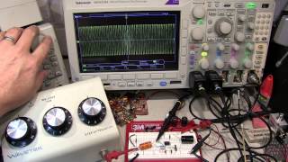
If you see the plot where the power is not on, there was already a loss at higher freq, presumably because of the inherent capacitances of the test board? His purpose was to show us the relative changes from opamp to opamp so it was not important.
If you are going to continue this topic, consider an inverting amp with gain varying from: -10 -> -1 -> -0.5, this offers the opportunity to discuss stability, BW, poles,etc. (What happened to the DVM?)
You set your cursor at -30 dB. For power, you want -3 dB. For voltage or current, you want -6 dB. Recall that 10 dB power is 20 dB voltage or current because P=I^2 R=V^2 / R.


Excellent video! Good job!
Great to see differences between original and fake op amps.. 👍
You forget the most important of your test: Output LOAD!
Op Amp is not voltage amplifier. It is a low power amplifier, then placing a load is a must. Without load the test have no purpose. Just check how manufacturer do test. It is always shown on each datasheet.
Since the output was no longer a sine wave, you were measuring slew rate not bandwidth. Bandwidth is a small signal parameter so you need to attenuate the input so that the voltage swing on the output is not slew rate limited. If you are slew rate limited the output will look more like a triangle wave than a sine wave.
Might be interesting to hear the "So what" of the op amp's phase data you covered.
that's above my pay grade
Great series !
Great video!
Why do you think your build on the OP07 rollled off about an order of magnitude earlier than the datasheet specifies?
I too sometimes find it difficult meeting some of the specifications given, recently have been struggling with choppers.
If you see the plot where the power is not on, there was already a loss at higher freq, presumably because of the inherent capacitances of the test board? His purpose was to show us the relative changes from opamp to opamp so it was not important.
least I know what scope 2 get! no mem button? yup! love them op-amp chip's
If you are going to continue this topic, consider an inverting amp with gain varying from:
-10 -> -1 -> -0.5, this offers the opportunity to discuss stability, BW, poles,etc.
(What happened to the DVM?)
Waiting for a part. Tomorrow
@@IMSAIGuy Oh, I had assumed that since you reported a series of 7 videos that you had pre-recorded all of them,... my mistake.
no you are right, I WAS waiting for parts
@@IMSAIGuy LOL well I am still confused, but that is a normal state of affairs.
Cheers dan
Which model of Rigol oscilloscope??
ruclips.net/video/eaoHYWYLRV0/видео.html
Possible to measure it by NanoVNA with an external attenuator? Guess it might be quicker? (Mag of S21 and Phase of S21)
Vna only good for 50ohm systems
@@IMSAIGuy not to mention the disparity in frequency range,...
External signal generator works quite well for these things.
You set your cursor at -30 dB. For power, you want -3 dB. For voltage or current, you want -6 dB. Recall that 10 dB power is 20 dB voltage or current because P=I^2 R=V^2 / R.
take another look. I have it set at -3db
@@IMSAIGuy Sorry, I was looking at phase...