As an industry professional, I keep coming back to this. It's really useful for when I have to do something simple and cheap. Usually, I'm using big complex PMICs but this is a nice guide for a simple SMPS. Thanks!
Excellent guide Phil, goes into the right amount of detail needed for a proper implementation without getting lost into too much unnecessary theory. Thank you!
This is great information. One request Phil. can you do a video on Input EMI Filter Design for this Buck converter. Not many information is available in internet. say if this converter Fails in EMC Compliance test. How can we solve the problem. What are the design considerations for EMI filter design. It will be interesting as well as informative. Thanks
i had to do a schematic for a buck converter at my internship recently and this definitely helped clarify some of the stuff that I did (per the datasheet) better! The graphic calculator playground tip is something I'll start using too
Excellent video as always! Up until now, I've always selected the components "by feel". Step by step your videos help me to build a better understanding of creating electronic circuits and who knows, maybe I'll be able to make acceptable designs one day ;) Thank's for your work!
Thanks for this Phil. Very detailed. I'm currently designing a PCB in which I plan to implement a switching regulator component, so your explanation is going to be really helpful. I might even submit the finished PCB design for you to review
I recently designed my first SMPS PCB, and already ordered the PCB and components before I saw this video. I used the recommended components and layout from the AP63205 datasheet, but now I'm concerned that some components may be out of spec (low capacitance on the input/output caps, and low inductance). I do have an electronic load and oscilloscope, so I'm planning on testing the SMPS at various static and dynamic loads. What sorts of problems should I watch out for? Is voltage stability the primary concern? What about EMI? Your channel is great! I have a software background with no formal training in electronics hardware design, but your channel and a few others have been amazing learning resources. Thank you!
The datasheet recommended component values worked out well for me. Parts arrived, and I assembled and tested it last night. Using a standard scope probe at 1X with the floppy ground lead, I'm seeing a 10mVpp ripple at 2.2kHz regardless of current. Under load steps between 100mA and 1A it's spiking +/-100mV but recovers within ~30us. Compared to my cheap benchtop SMPS, my PCB circuit exhibits lower ripple, lower noise, and a faster response to the dynamic load. I couldn't be happier for my first attempt at this!
16:00 - the video seems to be missing a few seconds there as you were talking about the precision of the resistors being important and it just stops midsentence.
Excellent video, as usual. Your presentation style is really great. I would love to see a video about some the theory behind the different types of compensation networks used in the more involved dc converter designs.
Thank you very much. I've designed a board (that still needs to be manufactured) that I wanted to use to show how to design a control system (digital) for a buck converter. Hopefully that'll show some compensation techniques, albeit digital.
Would be awesome to see this circuit in real life, so we can poke around the switching node and output to see the switching characteristic :) I remember learning a lot from this, to get a more intuitive feeling of the workings, instead of just drowning in the equations! Other than that; yet another very informative video 🤞🏼
@@PhilsLab FYI, I DIY'd a PCB yesterday using your guide lines for a 12v - 300V DC converter.... Wow. Practically noise free and without doubt the best I've made so far.
Hi Phil, thank you so much for your really informative videos. I was wondering if you can make a video of how to obtains a CE certification for low voltage device, and in general what are the design suggestion/consideration to don't fails the EMC test.
9:46 We calculated Lmin 22uH and we chose part with that value but datasheet says its tolerance is +/- 20%, so it is possible that actual value will be below our Lmin. Is that correct?
Hi, great video and well explained as usual. I have one question about the requirements specification, for a new project how can I know what would the load current be ? I guess there is no formula to calculate it and I have to guess it based on the components in the circuit but is there any rule of thumb to follow while choosing an output current? Thanks in advance!
Great video!! I have a question: How can you calculate point 2 @7:35 if your switching frequency isn't fixed as your case but rather variable depending on the output current as in the MIC2251 datasheet?
You'll have a nominal current that your design will require, so use that. Otherwise, design for the worst case (e.g. lowest current -> largest inductor).
Here's what I would do. Seach Texas Instruments Webench. Select DC/DC converter. Type in your input/output requirements and then submit and select which one is cheapest with the fewest components. Then save the generated files. Am I missing something?
Is it okay to choose the same bulk ceramic capacitors (e.g., 47u) for both the input and output, even though the voltage rating should be different? For reducing the BOM count
Don't use larger capacitances than required on the output of a SMPSU unless you want to add a pole reducing the transient response. 10uF was the correct value to use.
Thanks, Remy! Larger sizes are easier to solder, probe, and will typically be available in higher voltage ratings. However, smaller packages will have lower (lead) inductances, which is important for certain circuitry.
How could I use the information you provided in this video to make this a Current regulator? I am trying to build a circuit for a fiber laser and I need to be able to variably output up to 10A. I am having a hard time with IC selection and figuring out what components would be best for this amount of power. I'm using a 12v power supply. Any ideas? Maybe a video like this one but for a switching constant current regulator?
Does the footprint of the input & output capacitors make a difference here, assuming that the voltage and temperature are within limits of the caps? For example, if I can get an 0603 output cap that meets my requirements, is there any benefit to going with an 0805 of the same capacitance value? Just wondering why I often see larger footprint caps used on the SMPS than elsewhere on the board.
Hello, Could you make a video on how stm32 HAL works? Meaning why there are all these drivers , call back, macros and how do they connect all together. I'm sure there will be a lot of listeners.
You are one of my reasons to love the British accent. I like your voice. You look like a voice over artist. Could you tell me what is the difference between basic and extended part in electronics? I usually hear you in many videos say that this component is an extended part but I don't know what it is. Thank, Phil.
Thank you - I'm still waiting for someone to contact me for voice-over work however, I'm afraid :( Difference between basic and extended parts refers to the JLCPCB parts catalogue. On their site, for assembly, you pay a surcharge for using components that are not on their 'standard reels'. These are extended parts.
@@PhilsLab I appreciate your fear as a new step but don't make your fear control you. I hope you do well in this work. I really enjoy when I hear you, I bet that one day you will be a professional voice over artist, especially you have a powerful voice tone. I have understood that the extended part won't affect me in design except when I order SMT assembly, I will pay a surcharge. Is that right?
Did you ever get across audible noise on switching regulators? I had those issues with TI parts some time ago. Texas Instruments has a whole list of regulators with audible noise issues (even their EVBs). Maybe it's a feature for science fiction movies that you can hear electronic switching noise. MPS has a good online calculator for various values. The audible noise issue is also known to MPS however they really try to do their best to move the noise out of the audible domain. Not all switchers are affected from TI of course (they have a very broad range of switchers).
Surprisingly, I haven't had any issues with audible noise from switchers yet. I've used quite a few MPS and TI parts but haven't across noise like that.
Heyy.. your vidio are amazing 👏 can you plz help me where can I start my journey of electronic ( PCB design ) from basic can u suggest me the best vidio yours where it will help me to create my own Flight controller 😅 waiting for your reply 😆😀
One thing i've never really gotten a good handle on is the voltage and size properties of a ceramic. If i can get an 50V 0603 1UF cap, why would i use a 6.3V 0603 1UF?
Price, temperature derating, voltage derating, size.. all considerations.. A 0.1uf 50v 0402, for instance, will (almost always) have more voltage derating than the exact same part in an 0603 package. Take a look at the graphs for derating, and you'll begin to see why choosing what you need, but not over-specifying actually ends up being the better choice.
I have always HATED the back current flow in DUMB (vast majority) of synchronous bucks. The LT3800 is one of the RARE ones that fixes this. ANY THOUGHTS from your experience?????


As an industry professional, I keep coming back to this. It's really useful for when I have to do something simple and cheap. Usually, I'm using big complex PMICs but this is a nice guide for a simple SMPS. Thanks!
Thank you very much - I'm glad to hear that!
Excellent guide Phil, goes into the right amount of detail needed for a proper implementation without getting lost into too much unnecessary theory. Thank you!
Thank you very much, Ioannis!
This is great information. One request Phil. can you do a video on Input EMI Filter Design for this Buck converter. Not many information is available in internet. say if this converter Fails in EMC Compliance test. How can we solve the problem. What are the design considerations for EMI filter design. It will be interesting as well as informative. Thanks
Thank you, Anil. Yes, definitely - I'd like to cover more EMI/EMC topics and will try to make videos on that in the near future.
Onsemi (now TI) has a great paper available online, that covers it.
i had to do a schematic for a buck converter at my internship recently and this definitely helped clarify some of the stuff that I did (per the datasheet) better! The graphic calculator playground tip is something I'll start using too
Awesome, glad to hear that! Good luck with your internship :)
Where are you from and where did you do internship i am also wanted to do internship there
I'd be grateful for a video on the power supply for STM32H7 family. Thank you for great videos
I've recently sent a board off for manufacturing featuring an H7. Will make videos on that when I have it in my hands :)
Excellent video as always! Up until now, I've always selected the components "by feel". Step by step your videos help me to build a better understanding of creating electronic circuits and who knows, maybe I'll be able to make acceptable designs one day ;)
Thank's for your work!
Thank you! Glad to hear the videos have been helpful. Hope everything goes well with your designs :)
Your videos are very educative! And I like the topics that you usually talk about
Thank you very much! I'm glad that you like the selection of topics as well :)
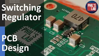
Thanks for this Phil. Very detailed. I'm currently designing a PCB in which I plan to implement a switching regulator component, so your explanation is going to be really helpful. I might even submit the finished PCB design for you to review
Awesome, thank you, Al - glad to hear this is useful. Hope to see your finished PCB soon! :)
I recently designed my first SMPS PCB, and already ordered the PCB and components before I saw this video. I used the recommended components and layout from the AP63205 datasheet, but now I'm concerned that some components may be out of spec (low capacitance on the input/output caps, and low inductance). I do have an electronic load and oscilloscope, so I'm planning on testing the SMPS at various static and dynamic loads. What sorts of problems should I watch out for? Is voltage stability the primary concern? What about EMI?
Your channel is great! I have a software background with no formal training in electronics hardware design, but your channel and a few others have been amazing learning resources. Thank you!
The datasheet recommended component values worked out well for me. Parts arrived, and I assembled and tested it last night. Using a standard scope probe at 1X with the floppy ground lead, I'm seeing a 10mVpp ripple at 2.2kHz regardless of current. Under load steps between 100mA and 1A it's spiking +/-100mV but recovers within ~30us. Compared to my cheap benchtop SMPS, my PCB circuit exhibits lower ripple, lower noise, and a faster response to the dynamic load. I couldn't be happier for my first attempt at this!
16:00 - the video seems to be missing a few seconds there as you were talking about the precision of the resistors being important and it just stops midsentence.
I wish I had this video about 2 years ago.
The slide and the presentation is awesome. Thank you.
I need the slide and the schematic and PCB. Thank you indeed
amazing amount of quality in these video's! can't believe this is free to watch.
Excellent video, as usual. Your presentation style is really great. I would love to see a video about some the theory behind the different types of compensation networks used in the more involved dc converter designs.
Thank you very much. I've designed a board (that still needs to be manufactured) that I wanted to use to show how to design a control system (digital) for a buck converter. Hopefully that'll show some compensation techniques, albeit digital.
@@PhilsLab Cool! Looking forward to that!
Would be awesome to see this circuit in real life, so we can poke around the switching node and output to see the switching characteristic :) I remember learning a lot from this, to get a more intuitive feeling of the workings, instead of just drowning in the equations! Other than that; yet another very informative video 🤞🏼
Good information. Now I can design a switching power circuit by using the existing “typical” application circuit. Thanks for that!
Nice revision of the formulas. Cheers Phil.
Thanks, Bart!
Excellent presentation and great information. Very clear and easy to understand.
Thank you!
@@PhilsLab FYI, I DIY'd a PCB yesterday using your guide lines for a 12v - 300V DC converter.... Wow. Practically noise free and without doubt the best I've made so far.
Phil, you're fantastic, sir.
Absolutely incredible video, great job!
I like these kind of video's with example calculations. I also hope you will create one testing this circuit and viewing some signals on the scope
Thanks, Joost - definitely will do!
Great Video Phil - Thanks for producing some great and informative content
Hi Phil, thank you so much for your really informative videos. I was wondering if you can make a video of how to obtains a CE certification for low voltage device, and in general what are the design suggestion/consideration to don't fails the EMC test.
Hey Phil, Great video. I had shared a buck converter schematic for review to your email. It could be a learning curve for others.
Thanks, George. I've seen your email - sorry I haven't gotten to it yet. I've received quite a few designs for review.
9:46 We calculated Lmin 22uH and we chose part with that value but datasheet says its tolerance is +/- 20%, so it is possible that actual value will be below our Lmin. Is that correct?
Hi, great video and well explained as usual. I have one question about the requirements specification, for a new project how can I know what would the load current be ? I guess there is no formula to calculate it and I have to guess it based on the components in the circuit but is there any rule of thumb to follow while choosing an output current?
Thanks in advance!
Great video!! I have a question: How can you calculate point 2 @7:35 if your switching frequency isn't fixed as your case but rather variable depending on the output current as in the MIC2251 datasheet?
You'll have a nominal current that your design will require, so use that. Otherwise, design for the worst case (e.g. lowest current -> largest inductor).
@@PhilsLab thank you so much for taking the time to answer my question, Phil! please keep it up with your videos
Please do one video for the Boost Converter aswell.
Incredible video as always.
Thank you - yes, I'll be making videos on other topologies as well.
Oh My god thanks for that. Greats from Argentina.
Thanks for watching, Gaston.
Great job Phil,thanks for the informative presentation
Do we need to take the load input cap into account when calculating the output cap of the smps
Here's what I would do.
Seach Texas Instruments Webench. Select DC/DC converter. Type in your input/output requirements and then submit and select which one is cheapest with the fewest components. Then save the generated files.
Am I missing something?
Is it okay to choose the same bulk ceramic capacitors (e.g., 47u) for both the input and output, even though the voltage rating should be different? For reducing the BOM count
Don't use larger capacitances than required on the output of a SMPSU unless you want to add a pole reducing the transient response. 10uF was the correct value to use.
Great video! Is there an advantage for the converter to take a bigger capacitor package, like 1210 instead of 0402?
Thanks, Remy! Larger sizes are easier to solder, probe, and will typically be available in higher voltage ratings. However, smaller packages will have lower (lead) inductances, which is important for certain circuitry.
How could I use the information you provided in this video to make this a Current regulator? I am trying to build a circuit for a fiber laser and I need to be able to variably output up to 10A. I am having a hard time with IC selection and figuring out what components would be best for this amount of power. I'm using a 12v power supply. Any ideas? Maybe a video like this one but for a switching constant current regulator?
great video but it seems like there was an editing mistake at 11:04
Does the footprint of the input & output capacitors make a difference here, assuming that the voltage and temperature are within limits of the caps? For example, if I can get an 0603 output cap that meets my requirements, is there any benefit to going with an 0805 of the same capacitance value? Just wondering why I often see larger footprint caps used on the SMPS than elsewhere on the board.
excellent video. thanks!!
Hello,
Could you make a video on how stm32 HAL works? Meaning why there are all these drivers , call back, macros and how do they connect all together. I'm sure there will be a lot of listeners.
You are one of my reasons to love the British accent. I like your voice. You look like a voice over artist.
Could you tell me what is the difference between basic and extended part in electronics? I usually hear you in many videos say that this component is an extended part but I don't know what it is. Thank, Phil.
Thank you - I'm still waiting for someone to contact me for voice-over work however, I'm afraid :(
Difference between basic and extended parts refers to the JLCPCB parts catalogue. On their site, for assembly, you pay a surcharge for using components that are not on their 'standard reels'. These are extended parts.
@@PhilsLab
I appreciate your fear as a new step but don't make your fear control you. I hope you do well in this work. I really enjoy when I hear you, I bet that one day you will be a professional voice over artist, especially you have a powerful voice tone.
I have understood that the extended part won't affect me in design except when I order SMT assembly, I will pay a surcharge. Is that right?
Just an addendum for input caps - know your DC bias derating (e.g. from the manufacturer's website).
Thanks a lot and please can you make more videos teaching Kicad ?
How come both the input and output capacitors turn out to be ceramic capacitors? Shoudn't one of them be electrolytic or tantalum?
Did you ever get across audible noise on switching regulators? I had those issues with TI parts some time ago. Texas Instruments has a whole list of regulators with audible noise issues (even their EVBs).
Maybe it's a feature for science fiction movies that you can hear electronic switching noise.
MPS has a good online calculator for various values. The audible noise issue is also known to MPS however they really try to do their best to move the noise out of the audible domain.
Not all switchers are affected from TI of course (they have a very broad range of switchers).
It also depends on your choice of inductor and capacitor. Both can act as loudspeakers (ceramic caps aren't that different from piezo tweeters...)
Surprisingly, I haven't had any issues with audible noise from switchers yet. I've used quite a few MPS and TI parts but haven't across noise like that.
What sizes of input and output capacitors did you use ?
Awesome video.
Thank you!
bro your voice is great
Please upload input emi filter circuit design
Dont we need electrolytic capacitor instead of ceramic ones?
Excellent 👏
Thanks, Ravindra.
Heyy.. your vidio are amazing 👏 can you plz help me where can I start my journey of electronic ( PCB design ) from basic can u suggest me the best vidio yours where it will help me to create my own Flight controller 😅 waiting for your reply 😆😀
Thank you very much
Thanks for watching, Mahmoud!
Fantastic!
Thanks!
Thank you!
Good vidéo, tank you
One thing i've never really gotten a good handle on is the voltage and size properties of a ceramic. If i can get an 50V 0603 1UF cap, why would i use a 6.3V 0603 1UF?
Price (in some cases)
size of cap smaller voltage is smaller size
Price, temperature derating, voltage derating, size.. all considerations..
A 0.1uf 50v 0402, for instance, will (almost always) have more voltage derating than the exact same part in an 0603 package.
Take a look at the graphs for derating, and you'll begin to see why choosing what you need, but not over-specifying actually ends up being the better choice.
you got it...
I can choose 360p or 1080p premium....
While waiting for the boost components video…..
pls your slide
💕
I have always HATED the back current flow in DUMB (vast majority) of synchronous bucks.
The LT3800 is one of the RARE ones that fixes this.
ANY THOUGHTS from your experience?????
There is NO diode in you choice, it is a SYNCHRONOUS controller+switch IC.
Thank you very much
Thanks for watching!