
- Видео 129
- Просмотров 94 911
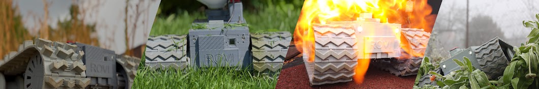
Rovi
Добавлен 19 ноя 2023
I'm a student at a high school and Rovi has been my project for more than two years now. The goal is to develop my engeneering, coding, problem solving abilities and making these videos helps me to improve language, presentation, and self reflection skills as well as inspire others to build projects like this.
Suspension test
Seeing how the new prototype holds itself in the face of the biggest enemy, drummm roll pleaseee, a mat. It's interesting to see the suspension work in this monitored environment as we can remove most external variables this allows us to focus more on the suspension. There were couple of problems with the suspension that we will have to solve going forwards.
Просмотров: 439
Видео


Making custom circuitry PCB and housing for vibration motors
Просмотров 364День назад
Having these four vibration motors in a controller helps to create additional output of information for user. They can be configured for any use on the code. Because there are four of them, they can create localized vibrations of various durations and strengths meaning that you can configure them to give user tons of important info. I want to thank PCBWay so much for providing these PCBs. Check...

Putting Aluminum Skeleton in my ROBOT
Просмотров 6114 дней назад
Just a short video of assembling aluminum skeleton and putting in in the robot. This is only a 4 minute video, but behind the scenes it took more than 12 hours from design, measuring, cutting with angle grinder and drilling in the aluminum, improvising, drilling again and repairing and so on. :D If you like this type of content, please let me know by clicking the thumbs up button, subscribing o...

New version of custom controller PCB with help from PCBWay
Просмотров 12721 день назад
Unpacking a parcel from PCBWay which has PCBs inside. These will be the backbone of the second upgrade. So, as the part of the utmost importance to the project, we need to test it thoroughly. Don't forget to subscribe to stay in the loop and keep up with updates. I want to thank PCBWay so much for providing these PCBs. Check out their website and get your US$5 welcome coupon for free with your ...

NEW vs OLD robot version
Просмотров 54921 день назад
Comparing current robot and a prototype version. There are some big upgrades, especially the big motor with high torque and the new suspension system. There still are many problems and many issues. The plan is to find as many problems as possible with it so that in the next version I can solve them. If you like/dislike or if there is something about the robot you would do differently/improve le...

Testing control distance
Просмотров 25Месяц назад
Testing the distance of control between android app and a controller with ESP32 microchip. The thing is that the app uses regular WiFi connection to the robot which acts as access point, basically a WiFi router. Whereas the controller uses the same chip as the robot making the communication more compatible and it also uses bigger antenna. There is also a mode that I can use with the controller ...

Part 2 first version of custom controller to control ANY robot
Просмотров 471Месяц назад
The first version of the controller is finally finished and it works great with my robot. The idea is that the controller is open source and you can customize it to your needs. Meaning that you don't have to spent time designing your own controller, you can instead use this controller and don't lose customizability. Unscripted video, just talking about what I love to do. I want to thank PCBWay ...

First version of custom controller to control ANY robot part 1
Просмотров 279Месяц назад
The first version of the controller is finally finished and it works great with my robot. The idea is that the controller is open source and you can customize it to your needs. Meaning that you don't have to spent time designing your own controller, you can instead use this controller and don't lose customizability. Unscripted video, just talking about what I love to do. I want to thank PCBWay ...

Designing custom DC-DC voltage regulator on diy PCB
Просмотров 1,2 тыс.2 месяца назад
I designed this DC-DC voltage regulator with LM2596 chip for my controller project. It's function is to lower down the input voltage from the BMS - batteries - if you haven't seen the video about the 2S BMS - ruclips.net/video/4ZWASpv6YaQ/видео.html . It lowers it down from max 8.4V to 5V with about 3A maximum current but I would push it. More like 2A nevertheless it's more than enough. If you'...
Tutorial to design custom 2S BMS with PCB example.
Просмотров 7842 месяца назад
Tutorial to design custom 2S BMS with PCB example.
New PCBs from PCBWay and showing first controller design
Просмотров 3383 месяца назад
New PCBs from PCBWay and showing first controller design
Off-road robot driving slow motion #robot #offroad #fun
Просмотров 1865 месяцев назад
Off-road robot driving slow motion #robot #offroad #fun
ESP32 inside PCB won't connect to WiFi
Просмотров 3426 месяцев назад
ESP32 inside PCB won't connect to WiFi
Mowing the lawn with custom robotic mower.
Просмотров 1517 месяцев назад
Mowing the lawn with custom robotic mower.
Making robot move in a straight line using ESP32 and digital compass
Просмотров 4010 месяцев назад
Making robot move in a straight line using ESP32 and digital compass
Raspberry Pi 5 TenserFlow Lite installation problem
Просмотров 76Год назад
Raspberry Pi 5 TenserFlow Lite installation problem
Testing Rovi in snow, problem solving and testing FULL VIDEO #rccar #robot #problem
Просмотров 436Год назад
Testing Rovi in snow, problem solving and testing FULL VIDEO #rccar #robot #problem
How to make custom tracks in Fusion 360 #fusion360 #3dprinting
Просмотров 102Год назад
How to make custom tracks in Fusion 360 #fusion360 #3dprinting
Spur vs Planetary gearbox and gearbox ratios
Просмотров 24Год назад
Spur vs Planetary gearbox and gearbox ratios
See how different track design can impact the overall performance
Просмотров 53Год назад
See how different track design can impact the overall performance