
- Видео 11
- Просмотров 699 468
TM
США
Добавлен 11 фев 2023
Help with programming, Arduino, and basic electronics.
If you're reading this, well, you're probably only the second or third person to have done that.
If you're reading this, well, you're probably only the second or third person to have done that.
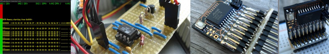
AVR ISP By Hand: Reading out signatures and other details.
Continuing the craziness of operating AVR ISP programming by hand. This video covers device signatures generally and shows reading them with switches and LEDs as well as other details of the ISP protocol such as /RESET signal behaviour.
Series playlist:
ruclips.net/p/PL6I82vVUc-ThORSCWi0s1OuWWK_hKmQLN
00:00 Intro
00:27 Entering programming immediately on power-up.
01:59 Regarding leaving the RESET state.
03:47 Signatures
07:17 Why you read signatures.
08:13 The signature read instruction
10:39 Filling in the general instruction form for the first signature byte.
11:45 Per-bit transaction overview
12:09 First signature byte
13:44 Second signature byte.
15:12 Third signature byte.
Просмотров: 1 084
Видео


AVR ISP By Hand: Demo Setup and ISP Programming Enable Instruction
Просмотров 1,3 тыс.Год назад
Doing the ISP programming by hand is a little nuts but it's interesting that you can do it at all. Seeing how it works can inform your understanding of how your wire in a programmer and the meaning of diagnostic messages from tools such as AVRDUDE. Series playlist: ruclips.net/p/PL6I82vVUc-ThORSCWi0s1OuWWK_hKmQLN 00:00 Intro 00:38 ISP's relation High Voltage modes 01:35 Cautions for experimenti...

AVR ISP By Hand: Intro/Teaser/Interest inquiry.
Просмотров 855Год назад
I'm curious to see what if any interest people have in seeing more about this. The chip on the board is at ATTiny13A, but could just as easy be any AVR microcontroller that supports the ISP programing method. Series playlist: ruclips.net/p/PL6I82vVUc-ThORSCWi0s1OuWWK_hKmQLN

Arduino Print and Stream Usage
Просмотров 536Год назад
Using the existing Print/Stream types to clean Arduino code and a bit about C inheritance and references. 00:00 Intro 00:14 Orientation and scope 01:03 Inheritance as related to Stream and Print. 05:25 Basic Example Function 05:47 Working without knowing Serial's type. 07:19 Regarding References 08:37 "Reference" terminology 09:12 Side-note about Pointers. 10:45 How the reference limits member ...

See the minimum needed for a USB device to list in Device Manager
Просмотров 623 тыс.Год назад
See a demonstration of how little has to go right for a USB device to show up in Windows Device Manager or Linux dmesg and understand what that means for troubleshooting USB microcontroller/Arduino projects. The video I'd mentioned about beginning regarding wasting time looking for drivers: ruclips.net/video/UdI7YQkXy5g/видео.html 00:00 Intro 00:15 Description 00:42 Demoboard overview 01:29 Dem...

Why a Digispark should not be your first Arduino.
Просмотров 42 тыс.Год назад
See the problems you can expect to run up against if you're going to try using a Digispark or Digispark-like board. I explain this in the video a couple of times but much of it is in text in the video. Just so that it is explained in text: These Digispark, clones of it, V-USB, Micronucleus, etc, are all fine if you know what you're getting into. Most beginners don't. And that's all I am to do i...

Arduino not showing Device Manager? It's NOT your drivers.
Просмотров 11 тыс.Год назад
This is why you can stop wasting time looking for drivers until you fix whatever is principally wrong with your Arduino. If your board has ever successfully uploaded code via its bootloader, odds are you do not need to go messing around with your bootloader, unless maybe you have a DigiSpark (or any board that doesn't have proper bootloader support). Usually you have a different problem. Most o...

Arduino ISP Mountable Single WS2812/"Neopixel" RGB LED
Просмотров 3,3 тыс.Год назад
You can make a nice single RGB LED to mount to your Arduino for testing purposes out of some. I've used it more than I expected to since making it a little while ago. This is intended for use at 5V. But it practice you can probably get away with it on the "ISP"/SPI header of 3.3V boards (or just given with a 3.3V logic in some other way). But you could build a passive voltage translation out of...

How to use the Arduino Nano BLE/Sense Watchdog
Просмотров 1,6 тыс.Год назад
How to use the watchdog timer on the on the Arduino Nano BLE, Arduino BLE Sense, Arduino BLE Sense Rev 2 or other boards with the nRF52480 microcontroller using only the register definitions from the CMSIS files with mbed_nano Arduino board support, including information about the watchdog interrupt. #arduino
IR Remote Testing With A Camera
Просмотров 2,2 тыс.Год назад
Useful for troubleshooting IR remote projects. If you've connected an IR emitter/blaster to an Arduino and can't even tell whether or not it's doing anything a all, this will tell you. #remotecontrol #infrared #arduino
You shouldn't add Strings in Serial.print() on Arduino
Просмотров 13 тыс.Год назад
Arduino Serial / Streams concatenate things for you. Doing it yourself is inefficient and less stable. As simple as it is, if you get out of the habit of doing this sort of thing, it'll generally improve your Arduino project code. Some of these patterns that are quite normal on desktop are not a good fit for a small microcontroller like a AVR that is in the Arduino UNO, Arduino Nano, etc. But t...
The Digispark design with two zeners in series (11:25) is scary. A short to ground would blow the 2V zener instantly and possibly short the 5V source as well. Replacing the 2V zener with a 1500 ohm resistor would be more robust.
Thank you I had it all wrong
Great video but I'm a bit confused, I don't see the 15k pull down resistors in your setup.
At 2:20 The vertical dashed line in the middle is supposed to separate the parts of the diagram that refer to host related stuff from device related stuff. The 15k resistors are on the host side. So you don't see them on the board, which is made to roughly model the device side of the line, or at least model the connection-pullup aspect of a device. The 15k resistors establish a reliable default low voltage on the host side until something is plugged in and tries to initiate a connection. Otherwise the signal voltage at the port would be "floating" (subject to electrical noise). Basically if the host side didn't have the 15k resistors, any time electrical noise registered as a high signal level at the port, the computer would attempt to start communicating with an empty port.
@@TM-zs7ko Ah okay, thanks for the clarification. Looking forward to trying this out for myself.
Hilarious! I'm sure tons of people purchased a fake USB flash drive only to find this was the circuit used.
i replicated this only using 2 resistors to divide the 5 v into 2.5
if mine shows up in linux but not on windows what should i do?
If it's the same board, on the same port, with same cable, but booting windows on a dual boot machine, and it doesn't list as an unrecognized device (at a minimum), then I'm not sure what would cause that. Is that the situation you're in? Or are you using multiple computers? Or...?
Years ago I could debug RS232 connections and tell you anything you wanted to know about it. Today USB is a mystery - I plug it in and (usually) it works. Very interesting to learn about the most basic aspect of how USB works. Thanks for taking the time to post this.
Just use a USB to rs233 chip.
I miss XP when you got the triple-bong to let you know the USB device had malfunctioned on connection, rather than a connection tone followed by a generic notification like in 10
Nice video. Do you happen to have any recommendation for a gpio-driven usb line reset? A couple of years ago I wrote a bootloader for an atmega32 running at 5V, which I configured to jump to user code unless a message from the host would be received before a given timeout. Whenever I wanted to re-flash user code as part of the regular development cycle, I don't quite remember, but I think I used to use a 10K pullup between the usb power line and a gpio pin. User code automatically included a stub that would act on such pin whenever a given control message was received from the host, meaning "physically" disconnect the line, which in turn caused the mcu to reset. The host-side tool I wrote would send this "reset" message, sit for a given time, and then try intercepting the bootloader in order to send the new firmware. This worked like a charm (on linux, never tried on windows), but I'm now left wondering if it's there any less hacky or more appropriate way of doing it.
Now i wanna see how it becomes qc and pd
Fried cracked voice 😤
So I can, with a 555 timer and some components, make a device that repeatedly plays the USB connect and disconnect sound from any computer I plug it into... good to know
This video makes me want to make a USB device. Great video, I like how you explained things!
i had problems so many times with usb and drivers are almost never the problem
You don't even need the resistors for data line on your board...
Yeah, thanks.
What happens if you throw both switches on at the same time?
Huh, that voltage regulator chip looks just like a transistor.
4:41: "The speeds higher than 12 megabit[s]..." Didn't you mean "12 megabits OR higher," since that's where you said the division is between high-speed and low-speed?
* "Connected to the USB." (No such thing as a "USB bus.")
This is great starter info. Now I feel motivated to learn a little more. I hope u have more follow up videoes to this to get to the next step to making USB devices
9:25 no, the USB standard specification clearly states that charge-only cables have short circuited D+ D- serial data line pins. Cables with no data pin connections whatsoever are fake / not USB.
wow this is SUCH high quality content, thank you so much :)
The software I develop runs on powerful Apple Silicon processors. However, I carefully examine every single dynamic memory allocation in my code and consider whether it is truly necessary. Dynamic allocations are often the slowest aspect of my computationally intensive code. After addressing dynamic memory allocations, the next thing I focus on is divisions.
I really appreciate this, this has helped me understand how USB handshakes start, without needing to read documentation
Thank you for sharing your knowledge with us. It was very interesting and informative :D
1:46 *OOPS: the color coding is correct for white and green, as the trace is broken under the switch. But the yellow is wrong, as it shows as “continuous” under the capacitor and resistors.* Either way, great video!
high grade content!
hey, I need help with my Digispark, it used to work a year back but now it doesn't. it is a bootloader problem? do i reflash the bootloader? Thanks.
Was it in operation for the last year or was it just sitting in storage? What exactly does it do when you plug it in?
@@TM-zs7ko it was sitting in storage. I have three of them. In one of the unused boards, it does run the blinking program, as i can see the onboard led blinking once plugged in. Update: I tried uploading the bootloader through Arduino ISP but it's still not getting detected by the PC. Thinking of using a high voltage programmer.
@@AnishSharma555 If it is uploading and verifying successfully through Arduino ISP, both flash contents and fuse values, high voltage mode programming isn't going to help. HVSP will help if you need to change one of the fuses, including any of those that would have prevented use of ISP. If the content of the fuses and flash are correct it doesn't matter which programing method(s) got you there. Digispark boards typically come with an older version of the Micronucleus firmware. Newer versions don't work with the upload tool shipped with the board support. But you may want to upgrade Micronucleus bootloader anyway, since it may fix some timing issues that then cause your board to show up. If you do that you'll either need to use something like ATTinyCore or alternately patch a newer version of the Micronucleus tool into official Digispark board support in the arduino15/packages/etc/etc directory.
@@TM-zs7ko thanks for the pointer. I'll try this and update.
Comment for Excellent Content <oh, and some fuggin' algo>
That's a great idea for a prank device to annoy the hell out of Windows users. A USB device that does nothing but connect and disconnect at random intervals.
Hmmm. Don't you need an ADC ? 😂 Every USB needs to identify itself by class and ID.
This video is amazing. I love the editing style, and the explanation is really crisp. You put a lot of thought into this! I especially love the way you explained each component and how it was connected. I understood perfectly without getting bogged down time-wise.
this assumes the puter doesnt require drivers installed... that was a head trip.. plug in the dongle for some programs on a new install... nothing. keyboard and mouse worked... listing as PS2. (but on usb?) so... how to get drivers on a PC to detect the USB if the USB doesnt have the drivers to detect a USB? cant download, its running XP, and its never going online... its for my CNC mill. unplug SSD and just copy files directly from other PC... i could have burnt a DVD but yeah... the drives not plugged in and i would have to change bios settings and to access bios requires removing the graphics card and last time i did that i then had to uninstall and reinstall the video drivers... because "linux". seriously, i dont get how a "relatively new" motherboard intended for win8 doesnt have native usb support, and to top it off... it HAS a ps2 port! i havent seen a ps2 device for twenty freaking YEARS!!!!! yes, it has a physical green and purple PS2 socket...
Just a good video that taught me a lot.
Learned a lot from this. Thanks.
Bros voice sound like a meeting with SEELE 💀 Great video tho, very informative
Someone in China be like: Hmmm maybe I can put all of this into a small package and slap on a 128 TB USB 3.0 sticker on it and sell it for 10 dollars on Amazon.
all you need is italy in your setup
Thank you for this video :) Subscribed
can you make a headphone jack a usb?
If it is a TRRS (4 conductor). Many mp3 players have used the headphone jack as a USB including I think some Ipod models.
why the voice changer
neato
This was so valuable!!! Thank you!!!
Thanks for the clear demonstration and discussion
Technically you don't even need a 3.3v regulator. You can just use a voltage divider to get 3v. Of course that's a little risky :).
You learn something new every day - at least I didn't know this when I got up this morning !
legit
OMG, wish I would have found your channels years ago. I'm a Coder from VMS days. Sometimes, the obvious is not always obvious. Pull up's/down wasn't clear in the beginning. And, you even give us a beautiful Wireshark screenshot, no less, an explaination of descriptors. The wonderful world of "record' data structures, aka, descriptors, and OOP. VERY Clear and "descriptive explanations!!! Add another subscriber!
Buddy Honestly, why isn't this the first video that shows up when I google it. You solved my problem. Thanks for the help.